
Michael Siggers
-
Posts
125 -
Joined
-
Last visited
Content Type
Profiles
Forums
Events
Articles
Marionette
Store
Everything posted by Michael Siggers
-
 @Tom W. Hi Tom Still, persisting with this. Watching loads of Vectorworks Videos etc. Simple Question: What layer am I supposed to be on when I create Site Modifiers? Trying the create a Property Line. Video shows this being done in 2 minutes. 30 Minutes later and I ma still trying. None of the videos cover this simple question. Mike
 -
Thank you @Tom W. Was just in the process of reading about that 🙂 Mike
-
Thank you Tom This is incredibly helpful. Very much appreciated. Interesting about Hardscapes as I thought they had to be created on the same layer as the Site Model. Mike
-
Thank you Tom This approach makes sense. Now just need to implement that for my project. I would assume that in plan view the terrain is turned off leaving the 3D Design and the OS Map showing below. Just trying to get my head around how to show the design, including the Car Partk etc. but show the wider OS map as surely the terrain would be in the way. In other words visable versus no-visable elements? Mike
-
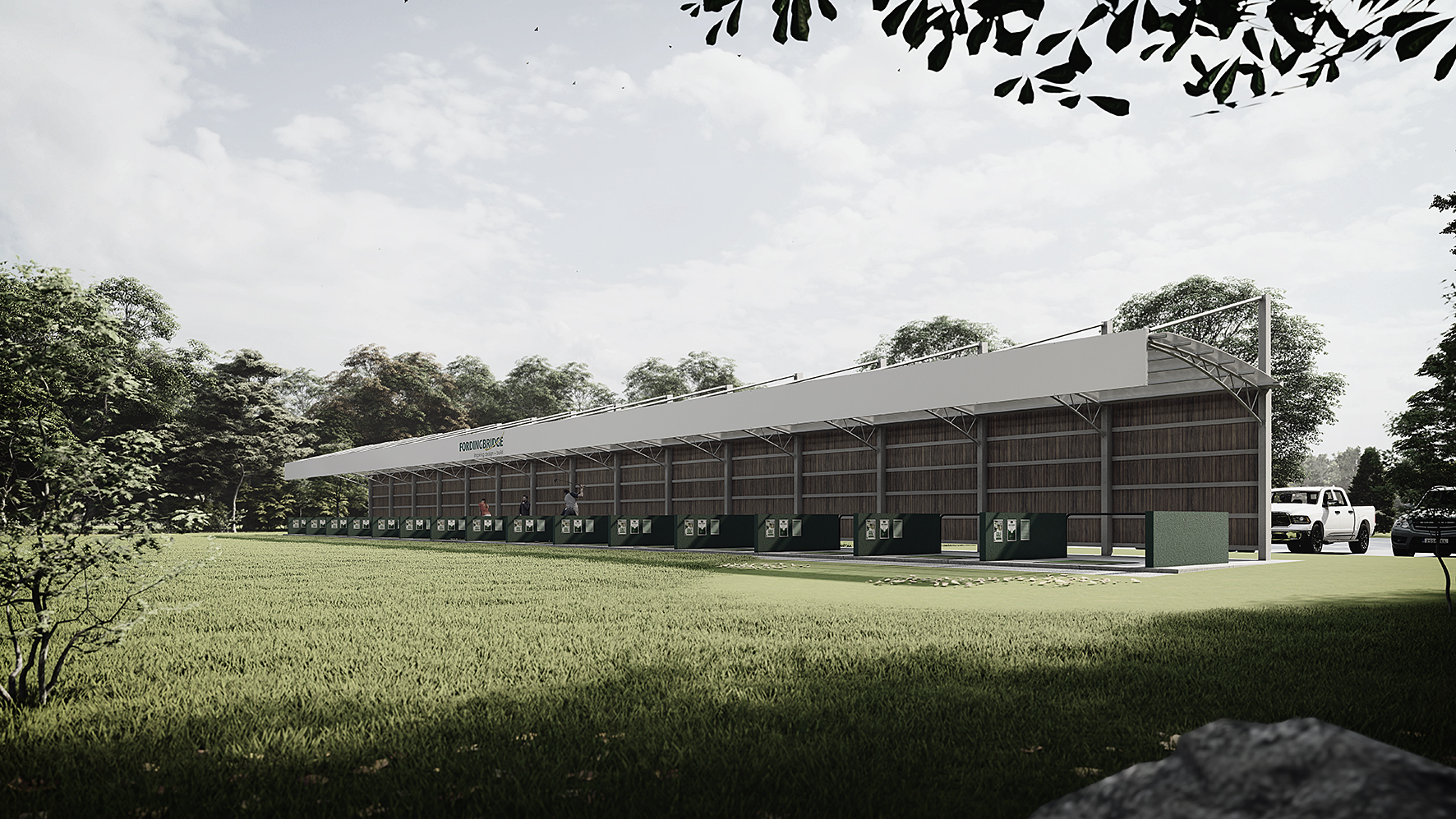
Hi Tom Yes, looked at a lot on the forum but no answers that I need. I managed to add a Texture Bed modifier but the line around it is non-existant. Essentially I need to show the Design on the Site Model to show various North, South, East, West Elevations so we can see the levels and relationship with surrounding buildings. I guess I need to rethink this then? Maybe drop the 3D elements on the Site Model so I can generate the elevations, then for the Plan view, switch off the Site Model, which will reveal the OS Map below, with the 3D elements will visible from plan view. Also, the Client does want a Rendering for the area involved, so I need to add in Car Parks and Markings etc. onto the 3D. Should be able to do that with Texture Modifier? Would be nice if the OS Map could be stamped onto the terrain though. Mike
-
Ah, no worries. So it doesn't matter whether it's a class, object, layer etc., if the name is the same, it can not be used? Mike
-
Send to Surface does this.......... attached screenshot. Mike
-
Oh, and just to say, this is a Practice file for a Project I am working on. Wanted to get the process correct before working on the actual file. Mike
-
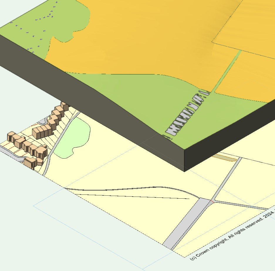
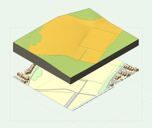
Just a bit of Background........ Attached is a screenshot. I am trying to transfer the OS Map areas shown below the Site Model to the Site Model itself as the Plan view will be used for a Planning Application. The Proposed Design is only using a small areas of this and I will use a Site Modfier - Pad for this. So far I am using the Site Modifier - Texture Bed, after selecting the various areas, (tedious), and it seems to work, although the lines between the areas are pretty much non visible. I could do with them being black like on the OS Map. Would be nice if I could just drape all the linework onto the Site Model and shade the areas, but hey, that would be too simple, unless there is a way and I am missing something. Mike
-
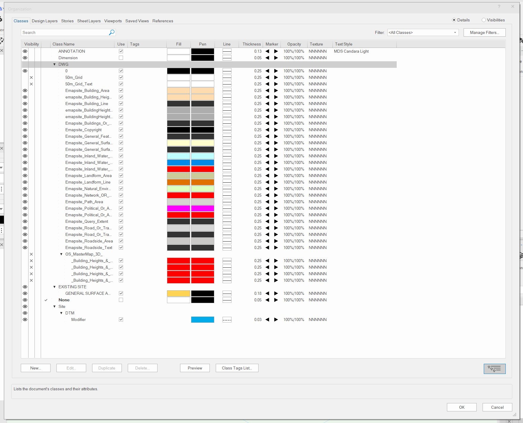
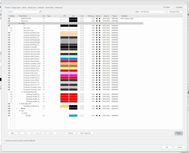
Hi Tom It states the Class Already Exists. I am trying to create a new Class. Screenshot attached. Kind regards Mike
-
Hi I have created a Site Model which currently is assigned the 'None' Class. When I try to create a Class called 'Site Model', it states it already exists but it is nowhere to be seen in my Class List. Have checked for Invisible ones too. Any thoughts would be appreciated. Kind regards Mike
-
Hi Hoping someone can help with some suggestions. I'm currently producing a set of drawings required for a planning application. I have created the site model from contours purchased from Ordnance Survey and also have the OS map, again from Ordnance Survey. The site model is at the same scale as the Map and when viewed from above, line up perfectly. The query I have is what is the best way to transfer the OS Map to the surface of the site model? Within the site model is an area where the design proposal will be, which I can create with Site Modifiers, but I would like the remaining area to show the OS Map, which shows houses, roads and green areas etc. The OS Map also includes the building in 3D which I would like to sit on the Site model. Kind regards Mike
-
Glad it is not just me then. That is exactly what I am having to do, and also ensure the option to switch them on and off is disabled in the OIP if set in the style. Maybe that is where the conflict is coming from? Mike
-
I'm finding there are plenty of those in vectorworks 🙂
-
Beautiful!!!!!!! Searched high and low for an answer an even on the instructional videos I could not see that they mentioned this. Thank you. Mike
-
Thank you Tom That worked ok. One last question is why when I generate terrain it appears miles from where the Contours were and not in the same place? I' assuming it has something to do with Geo referencing, but how do I stop it happening? Mike
-
Hi I have created a Site Model based on contours imported from AutoCAD and it has worked fine. However, because of the lack of contours at the corners, (it's a fairly non-descript site in terms of levels), the site model has missing corners which I would like to add, effectively making the whole thing rectangular. This is mainly for presentation reasons. So, what would be the best way of adding this additional 'site' to the Site Model? Effectively I want to add a rectangular boundary so when the site model generates in creates a Rectangular piece of land. Kind regards Mike
-
So Attached is a file which has two corner walls on. The one on the left was created with a Style that includes the External Cladding installed onto Vertical battens, and Internal Plasterboard installed onto battens to create a service void. The wall is constructed using SIPs with the internal and external finishes installed. I created a wall style that includes all the components. The one on the right is how it should look. This was created using a wall style for the SIP alone, (Structural Insulated Panel), and then the External Finish and Internal finish were modelled separately. As can be appreciated, this makes it a ball ache when inserting doors and windows. The $64000 question is, I bet there is no way to achieve what is shown on the right with the Wall Style on the left? If this is not possible, at least I know and I can stop wasting my time trying to sort it. Kind regards Mike Practice 19 - Wall Joining.vwx
-
Here are two Viewports with EXACTLY the same style applied. Too many bugs in Vectorworks!!!!!!!!!!!!!!!!!!!!!!!!!!!!!!!!!!!!!!!!!!!!!!!!!!!!!!!!!!!!!! Any ideas as to why the one on the right is not displaying correctly? It should be the same as the one on the left with muted, sesaurated, and over exposed colours. Causing way too many problems.

-
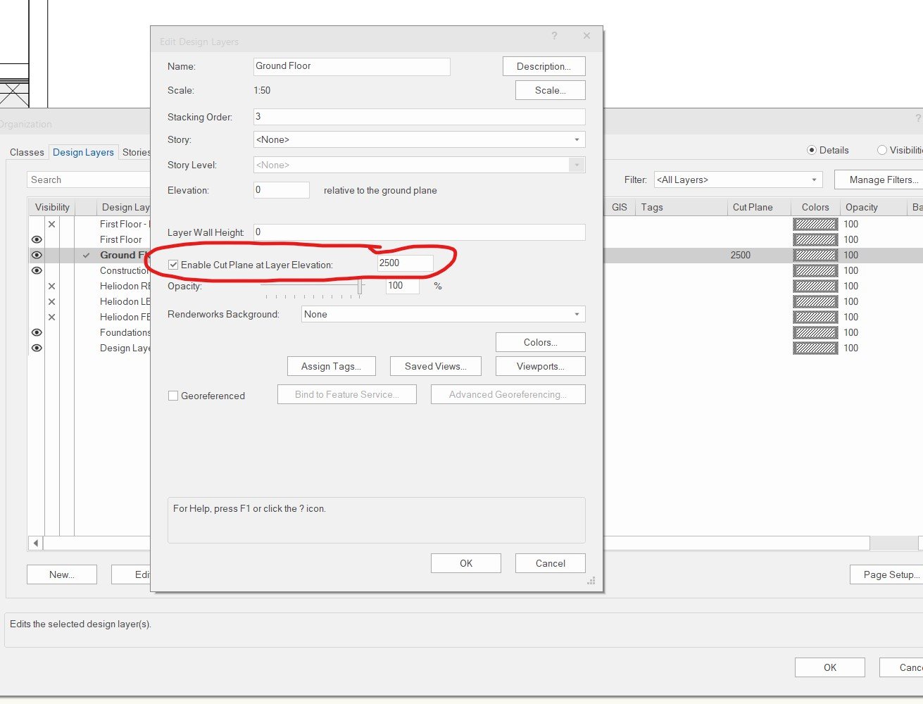
Layer Cut Plane at Elevation does not work
Michael Siggers replied to Michael Siggers's topic in General Discussion
And hence why my Roof Component is showing in the Top/Plan View. I have to hide the Class in the Viewport to remove it. Maybe Vectorworks can concentrate on getting features like this to work rather than revamping the User Interface. After all, I don't present the User Interface to my Clients. Mike -
As far as I can tell, the attached does absolutely NOTHING to change where the Top/Plan Section is taken. Same as Version 2023. Any thoughts? Mike

-
Missing files when trying to replace a wall style.
Michael Siggers replied to Michael Siggers's topic in General Discussion
Thank you @Pat Stanford I've struggled with it for too long. Just seems way less intuitive that Sketchup. It's a shame as I really wanted it to work out. The deletion of my Walls Resource file was the final nail in the coffin. Took me ages to set up various wall styles and now they are all gone. No sign of where it saved a Backup which it should have done, but I can not find it. I'll have to finish a couple of projects that I started in Vectorworks but other than that I will not be renewing my Subscription. I now have to start todays work all over again and it is 7.15 in the evening. Not happy! Mike -
Missing files when trying to replace a wall style.
Michael Siggers replied to Michael Siggers's topic in General Discussion
Back to Sketchup. Will be ending my scubscription to Vectorworks -
Missing files when trying to replace a wall style.
Michael Siggers replied to Michael Siggers's topic in General Discussion
Yes, I have