Jack2022
-
Posts
176 -
Joined
-
Last visited
Content Type
Profiles
Forums
Events
Articles
Marionette
Store
Everything posted by Jack2022
-
Ok thanks
-
Quite right Tom. I didn't explore slab drainage enough before moving on. Any advice on showing the grades as ratio not %? Thanks
-
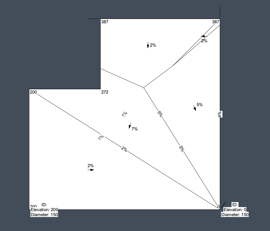
Hi All, I had raised the issue of how to make a hardscape have a tapered component before and the result was that they can't. i.e they can't have a sloped top and a fixed bottom. Well I've just found the solution which is slab drainage! Brilliant! Question: in the UK we show falls as a ratio not percentage. Is it possible to show the falls/ gradients as a 1:x ratio?? Many thanks.
-
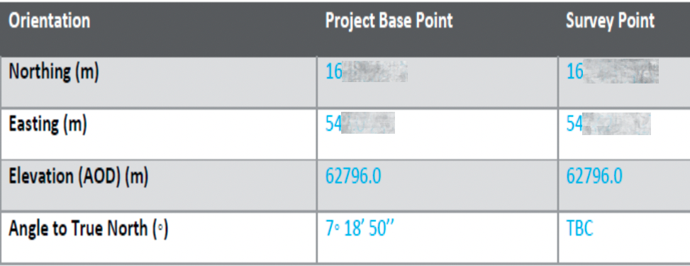
Hi all, I have approached this project elsewhere with some useful feedback but I'm still after a simple solution or if there isn't one, then a reason to challenge the BIM plan given to us by our client. As usual the BEP is Revit centric as the BIM coordinator isn't familiar with VW. We have been given shared coordinates which I paste below. Question: How can I set up my VW file to align with these shared coordinates? If its not possible then a quick reason why so I can feedback to the BIM coordinator would be helpful. I can do things partially by manually moving our model into position over their building but as usual the architect has drawn their building orthogonal not to true north hence the true north angle in the provided shared coordinates. Landscape is further down the food chain in our contract so we MUST align our model to match the architect's. The only excuse we have is if its simply not possible. Obviously if I rotate our model to match, we lose our coordinates as the User Origin doesn't rotate. We can get it in position but the angle to true north is where I'm lost. If I change the angle to true north of my model (using the georeferencing tool) then my x,y coords for a given location don't change. Its as if iv'e not changed anything. Many thanks in advance, Jack

-
Thanks Shorter. Im beginning to piece together fragments of what I need to know. To simplify the discussion and hopefully get to a resolution - How do I use the below info to set up a new vectorworks model? It's the shared coordinates info. Is there a step by step that specifically addresses this? Is there somewhere to input this info into the file? Kind regards, Jack
-
It seems both our models (my VW and their Revit) appear to share the internal origin point despite us not manually setting it. ie their model imports near my default internal origin and when they import my IFC it appears In position relative to their model as I see it on my screen. Even stranger the BIM coordinator using Navisworks to combine models has everything appear in the correct location regardless of where I locate my model. Something is probably being lost in translation across consultants
-
Revit and DWG so far - I have requested an IFC. as mentioned their DWGs import in real space coords and thats where we started our model but have now moved it near internal origin (about where their Revit model imports) Ultimately under our contract the Architect is lead and we need to make provisions so our model imports directly aligned with theirs. Thanks
-
Thanks Shorter, the BIM coordinator has made a BEP and provided project base point coordinates, survey point coords (same as PBP), rotation from true north and all the procedures. however the BEP assumes only Revit is used. What do I do with this coordinate info in Vectorworks? Do I need to set my internal origin to the project base point? If I import their revit model it appears very close to my internal origin. if I move and rotate my model to match their model then they receive it fine their end when I export as an IFC. I originally used their 2d DWG files to position my model however their DWGs appear in real space whereas their model appears near my internal origin. Obviously I can't build my model in real space otherwise it would be miles from the internal origin. Any more help would be appreciated - maybe a step by step of how to use the BEP coords in my file? Jack
-
Hi All, We need to align our landscape model with the architect's model and engineer's. Our model is aligned to true north - theirs to orthogonal on the x/y axis of the software. I can position our model in the correct location (very near Internal Origin) while retaining true Northing and Easting readouts by setting the User Origin where it needs to be relative to the Internal Origin. Problem arises where I need to rotate our model to align with theirs. User Origin coordinates do not rotate with the model obviously. Is there a way to not only move User Origin to maintain true project coordinates but also rotate User Origin to compensate for our model rotating to match theirs? Thanks Jack
-
Well I could see why that would be useful for rounding solids and extrudes but the mound I need to make needs to have set gradients hence the choice to use contours. Subdivision seemed very complex to control the control points. Investigating NURBS surfaces. Early promise! Now need to find out how to give it component type layers / separate internal layers each with different depths
-
Thankyou - ill give this a go
-
Thanks both. Could you elaborate on subdivisions and doing it using solids? I hoped this was simple thing to create a small smooth mound I can convert to a slab like structure/ site model/ landscape area? Im going round in circles trying to find out via videos. Jack
-
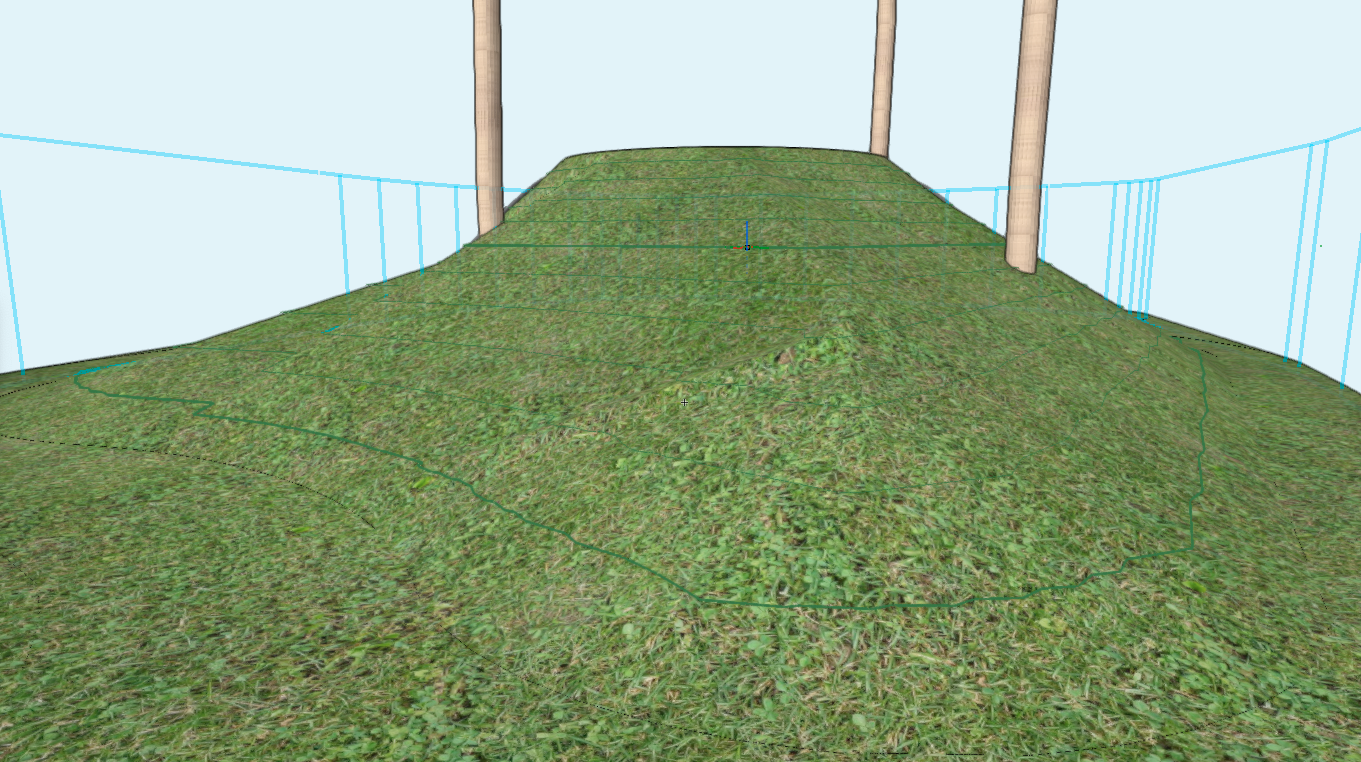
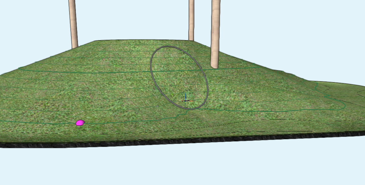
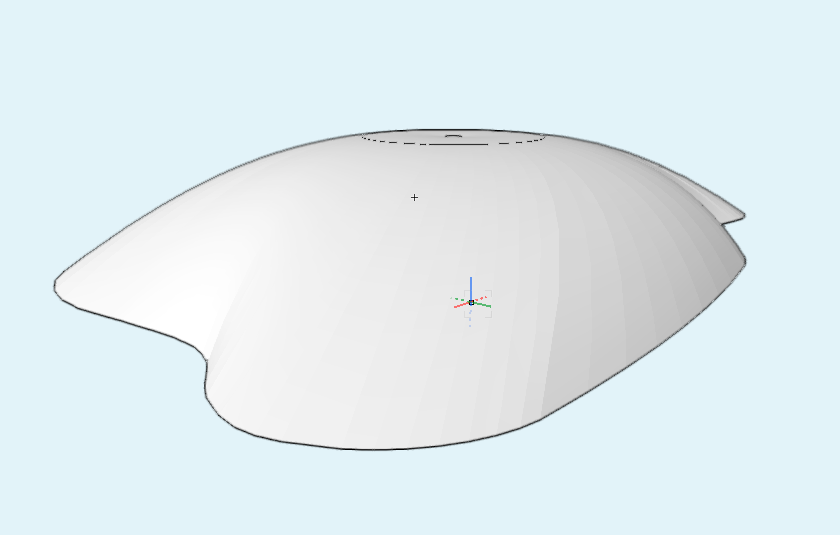
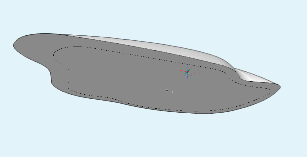
Hi All, is there a way to create smoother site model? Screen shots below. Is the only option to add more contours? as you can see Vectorworks doesn't seem to want create smooth contours itself. I have site model smoothing selected. Maybe use a different surface type? I still want components though. If I attempt to modify the contours I get crazy geometry shooting down to Z:0 which I can't fix. Thanks

-

Problem referencing 3D model for coordination
Jack2022 replied to Jack2022's question in Troubleshooting
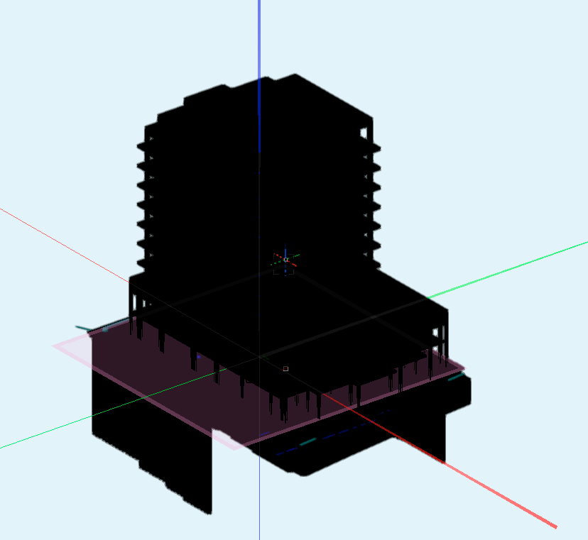
Ok I have solved the black model issue. This time select all change attribute fill colour worked. Same process as I tried before just this time it worked. To be clearer on the referencing: I don't want to combine live geometry of different consultants into ours nor modify any of their geometry - I simply want to have it showing in our model as an inert entity or solid object that can't be edited so it appears in our section viewports as context for our model. -
Hi All, We have our 3D landscape modelled and wish to bring in the structural engineer's model and architects model (although the architect's is too heavy for my computer!). I have imported the structural model from revit into an empty Vectorworks file to create a Vectorworks structural model. I don't want any data from their models. Just generic meshes/solids. I don't want to bring their models directly into ours as it will slow everything down. What's the simplest step by step? How do I best bring their models into my model as a reference? When I go to Organiser and create new reference linked to that file, while the reference appears in my reference list, the actual model doesn't appear in our model? Nothing just our model. As far as I can tell its not a visibility issue. Also why does each element of their model import into Vectorworks as solid black as per below screen shot? I found a way to mass convert all the meshes back to solid fill white bt its not working now. Thanks all,
-
@Jeff prince - is there a reason to keep the layers as meshes? What difference would making them generic solids create? Difference in data content, volume, area etc?
-
Hi Tom, I think the issue is I am not entirely sure what level data I need to output with the model! I am exporting IFC files for coordination and assigning generic building proxy IFC profiles to all components as there aren many if any landscape IFC profiles available. I am building a model that needs to be COBIE compliant for BIM level 2. I have a grasp of assigning material information to hardscape, slabs walls etc by adding data to custom materials. However when it comes to COBIE data I need to do more research.
-
I've had a play with the reports and I have an uneasy feeling this is where I will come unstuck with the required IFC/COBIE data for BIM. I tried a generic Hardscape report and it contains the overall hardscape but doesn't seem to pick up any of the component information despite me doing what it asks. Thanks for the pointers. One for me to investigate I think.
-
Editing Hardscape Shape Creates Distant, Invisible Geometry.
Jack2022 replied to Jack2022's question in Troubleshooting
Solved Many thanks for persisting -
Editing Hardscape Shape Creates Distant, Invisible Geometry.
Jack2022 replied to Jack2022's question in Troubleshooting
ah of course. thanks for clarifying -
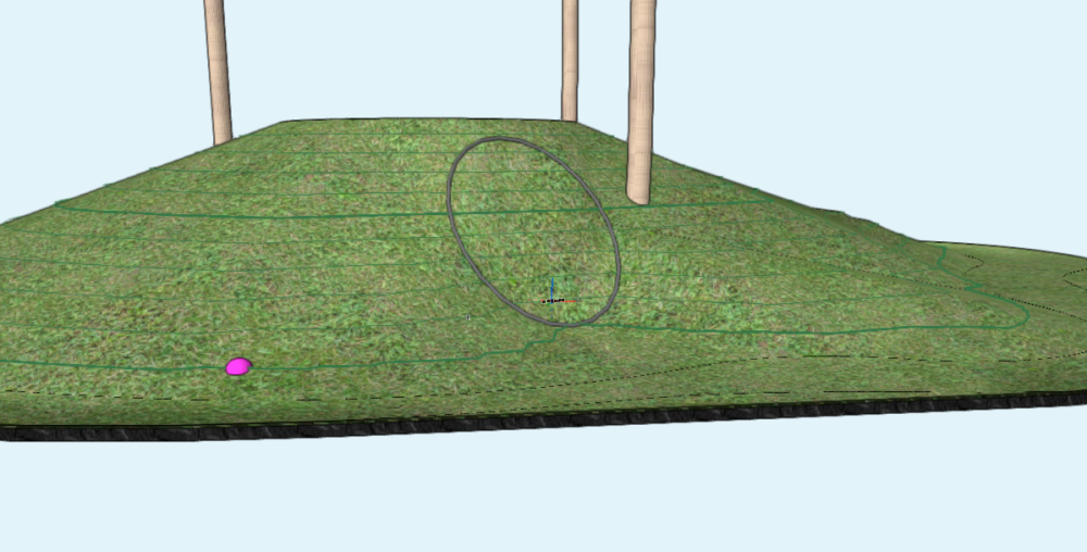
@Tom W. Hi Tom, I've been playing with this and have created a test mound as a site model, ungrouped it and looks good and has retained material info. As I mentioned in my follow up post I have now lost area and a volume information. You mention returning this via worksheets. Are you able to elaborate? My ultimate aim is to be able to read data from the model for BIM workflows once everything is built. In many cases I am building the model and attributing data post building hoping to then export as schedules of info. Many thanks
-
Editing Hardscape Shape Creates Distant, Invisible Geometry.
Jack2022 replied to Jack2022's question in Troubleshooting
Hi All, thanks for the pointers. If I set the User Origin close to the model (as in really close) then the problem still persists. Might it be a different issue? Thanks, Jack -
Sorry to labour the subject but will the un-gouped mesh objects still retain their data required for material spec call outs, volumes, areas for BIM? or do I need to do something to them to give them back this quality. In this case area, volume and materials. As you can tell I am new to BIM modelling. I always assumed that you can't just build an object similar to sketch-up as it won't have data fields or be dynamic. Rather you need to use VW (or revit etc) tools to make BIM complaint objects. I am beginning to gather, however, that you can build something in many ways, solids, meshes, symbols etc. and apply data to it after it is built. I do spend time in the Vectorworks University resource but most videos tell me I can do something but without revealing how! Hence becoming a regular on the forum. Anyway thank you for your help.
-
Thankyou! nice and clear I'll check out your other post and reply there. Thanks all.
-
Editing Hardscape Shape Creates Distant, Invisible Geometry.
Jack2022 replied to Jack2022's question in Troubleshooting
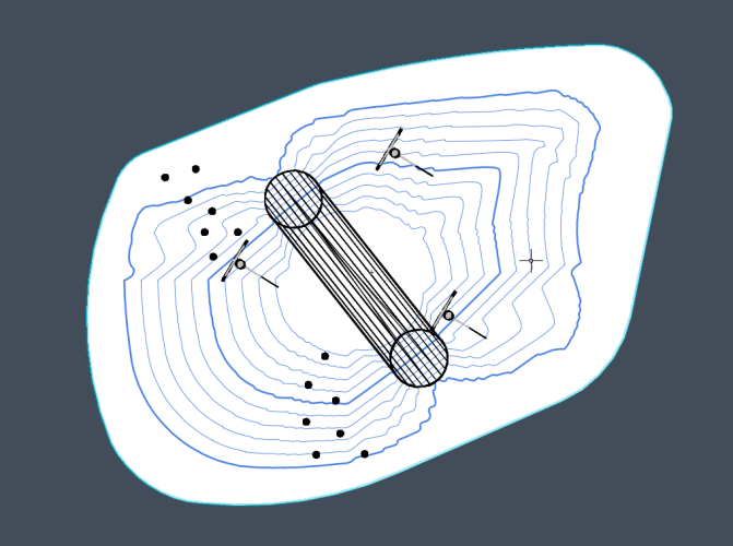
I have attached a small model that should help. If the vertex of the hardscape is edited then the problem occurs. Thanks for any help Mound test model.vwx