mwalker_mw
-
Posts
10 -
Joined
-
Last visited
-
Further to this - just had spotlight numbering stop working entirely (for applying cable numbers). You could do all the steps all the way through to the green checkmark but then, no numbers applied. Saved, closed VW, reopened VW and did the exact same steps and it worked as expected.... Also some oddities with loop-thru on a bottom connector. It puts the connector type on both sides making cable labels unreadable: (Generally, it would be great to have override checkboxes in the OIP for turning off the display of connector type, 'cable' field and similar. For when you want the data in the spreadsheet but not necessarily displayed for a particular item.)
-
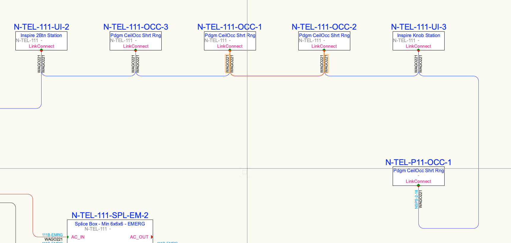
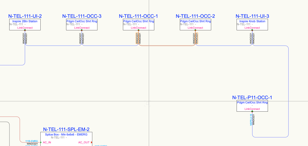
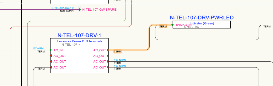
2024 latest on M1 Mac. It was very odd - I was even seeing different behavior between apparently identical items generated from the same 'Create Equipment' command and changing the same settings with them both selected. One would show it, the other would not. I've switched everything over to DataTags so I don't have a file to show it handy but will post if it comes back. (DataTags are proving much more flexible anyways...) I've seen a few other display oddities as well. In particular, identical devices in identical layout spacing with identical circuit routing (i.e. copy, paste, rename) in schematic view where cable numbers show up for one connection and not the other. I think I've figured out most of the logic for when it displays but there's been a few that seemed to be exceptions no matter what. For example: the highlighted cable has a number value '107-NRML' with Number Display set to auto. Plenty of room for the label but it doesn't show at either end. They display properly if forced, but not with auto. I'm rushing to get this drawing done but will try and log things a bit better when time allows. I've been able to figure out workarounds in most cases.
-
Thanks - that's a bit disappointing as I do like to create multiple views of the same topologies for clarity. I can still do it manually, but was hoping to automate somewhat. Wishlist would be to be able to create 'instances' of schematic devices that fully mirror and track their originals (including socket connections) but can be placed in separate arrangements with separate visual routing of the circuit path. That is, the instances are not editable beyond location and the path of the circuits in between but can be located separately, isolated from an otherwise complex drawing, and annotated as needed with all their other properties staying in sync with the originals. (Just saw Conrad's reply - yes, they can be shown as reports. But for visual people I find the line drawings are appreciated - even if it is the same data. I'll play around with the panel view suggestion - might cover some scenarios. Thanks.)
-
Interesting - with circuits selected it does, indeed, show the same tools. But, with nothing selected, choosing the one in the standard tool palette gives a completely different (and smaller) set of options in the top bar.
-
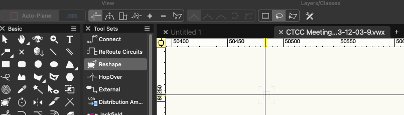
What you want does work. 1) Make sure to use the reshape tool from within the CC Schematics palette. (I have no idea how they are different, but they are - click between it and the regular one and watch the options change in the top bar) 2) Then select the circuits you want to change by shift+click on the lines. 3) Then use click and drag in the white space for reshape selection to grab the vertices you want (has the usual options for selecting). 4) Then click/drag any of the selected vertices and they will all move as one. There are the usual options for moving individuals, faces, etc. in the top bar. Not the most intuitive workflow... but figured this out after fighting with it yesterday.
-
Much as the title. When I have a text field in an Equipment Item linked to a custom record it shows correctly with the pink square. Switch on 'Use Symbol' and that text disappears. I've tried playing with layer order and does not seem to fix it. Am I missing anything or is this normal? (I'm trying a workaround with data tags with some success...)
-
Stumbled on this while trying to find a way to update a large number of devices. I can certainly see the logic of not updating the drawing indiscriminately - however, this process becomes quite tedious for large numbers of updates. May I suggest adding marquee select capability to the paint bucket tool? That is, with the tool selected clicking on a device updates the device - as it does now. Clicking not on a device starts a rectangular select that, when released, updates every device inside (subject to the filter settings such as 'same devices'). This would be a huge time saver.
-
What is the intended practice for representing multiple instances of the same device? For example: if I have an overall system topology drawn out but then I'd like to do a sheet that just summarizes patch bays and field plates with nice straight lines for ease of reading. Same devices but two different schematic layouts for two purposes on two different sheets. My expectation was that I could just copy/paste the devices keeping the names the same > select them > connect selected and the software would draw in a duplicate of the wire connection I'd already drawn on the originals with identical labelling, etc. That is, the software would assume that devices with duplicate names were the same devices and their connections should thus be synced between. But that didn't work. It did nothing. I then tried manually putting the connection back in and it treats it as a separate unique circuit. Despite connecting the same sockets none of the data syncs. There does seem to be a connection between device instances for labelling purposes. If I change the rack field for one instance it also updates the other. But the circuit/wire doesn't seem to behave the same way. What am I missing here? How should I be handling this? Similarly, changing the socket connector type on one device instance does not sync to the other even though things like the rack field do. Is there a summary anywhere of what does and doesn't sync? (the manual and google are failing me here...)
-
Thanks all. I do think it would really speed up use. Coming from a WYG background I also always appreciated the quick increment and decrement shortcuts that could be triggered while using the tool. In the meantime, however, even making the visible area of the fields for Prefix and Suffix longer would be hugely helpful (I'm using it for ConnectCAD and labelling can get lengthy). ... and while I'm at it... a 'recover' button for when you do all your selections and then click away, forgetting to click the checkmark. The WYG workflow just applied as one clicked. Not sure the reasoning for the additional step in VW when there is always Ctrl-z if you make a mistake. It's also a bit unfortunate there is no way to use find and replace on device names for a selected group of ConnectCAD devices. This would be even easier than Spotlight Numbering for repetitions of similar rooms...
-
Is there a means to have the spotlight numbering tool as a dockable palette? Switching into and out of it as a modal is very disruptive to workflow....