Alex Talbot
-
Posts
21 -
Joined
-
Last visited
Content Type
Profiles
Forums
Events
Articles
Marionette
Store
Everything posted by Alex Talbot
-
@Jesse Cogswell Just from a quick test, naming a loci and having it pull the XYZ data from the loci works perfectly. I'll have to play around and see how I can implement this effectively - renaming a loci to pull XYZ data isn't really any faster than just moving a created object, but I may be able to get creative here.
-
I have a set of menu command marionette scripts built to automate repetitive pieces of my entertainment drafting workflow, such as building video walls out of tile symbols, or building platforms from leg and deck symbols. Currently, my marionette scripts will place built object at the 0,0,0 origin when executed from a menu command. Optimally, I'd like to make it easier for the objects to spawn wherever I want in the drawing to save the step of moving the object after inserting it at 0,0,0. For example, I can place a 3D loci on a truss, and then spawn the video wall centered on the loci as opposed to moving the wall after building it. Going further, I'd love the capability to build an LED wall or stage based off of a 2D object. For example, I could draw a 2D rectangle where I'd like the LED wall to be placed, and then have a marionette script replace the rectangle with a built video wall of similar dimensions and location. Is any of this possible with stock nodes? I've dug around quite a bit and have found limited functionality for interactions with existing drawing objects. Thanks in advance!
-
@Letti R This is a significant improvement to my current duplicate array workflow, thanks!
-
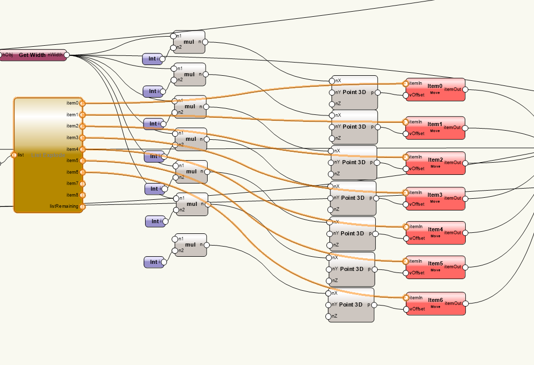
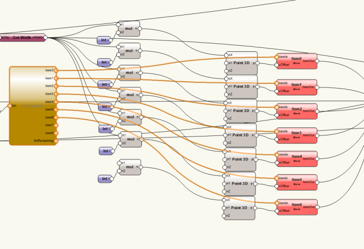
Back with another marionette question regarding 3D arraying, specifically in the X/Z direction. I'm working on a tool to make video walls from custom LED tiles in the symbol library, and the biggest hang-up I've run into is cleanly arraying in 3D with marionettes. Currently, my arrays rely on extensive duplicate, list, and move commands (shown below) that eventually hit a limit on how many rows and columns I can make. I've seen some tools on here posted to replicate a 3D array marionette, but none of them have worked effectively to solve this issue. Are there any clean workarounds here that I can try?
-
Hi All, Back again with another marionette question. I currently have a few marionette sequences used for creating essentially arrayed symbol objects for things like platforms and video walls. Inn the example of video wall tiles, the core logic is: 1. Import symbols from library 2. Duplicate symbols and array them across the X-Axis to create the number of columns for the wall 3. Duplicate that group of symbols vertically to create the number of rows up the Z-Axis This is effective for quick video walls, as long as I know the tile width/height in advance. What I'd optimally like to create is a version of this plugin that relies on physical dimensions instead of tile counts, similar to the "Overall Dimensions and Spacing" option on the built-in Spotlight video wall tool. E.G. if I have a 40ft x 60ft wall I can put a LED Wall on, and I only have 60cm x 60cm tiles available, the marionette can get me as close to 40ft wide x 60ft high with my premade symbols as possible. Is something like this possible with marionetting? Or is this logic too complex to build with marionette nodes?
-
Rotating 2D Line Vertically for Mirror Ball Marionette
Alex Talbot replied to Alex Talbot's topic in Marionette
Thanks! 3D poly was the best solution. -
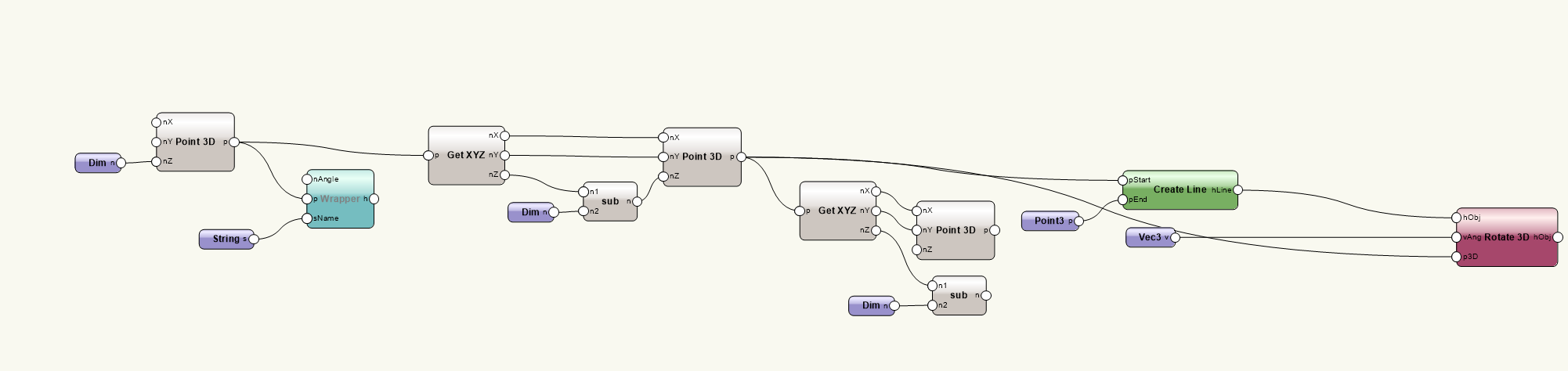
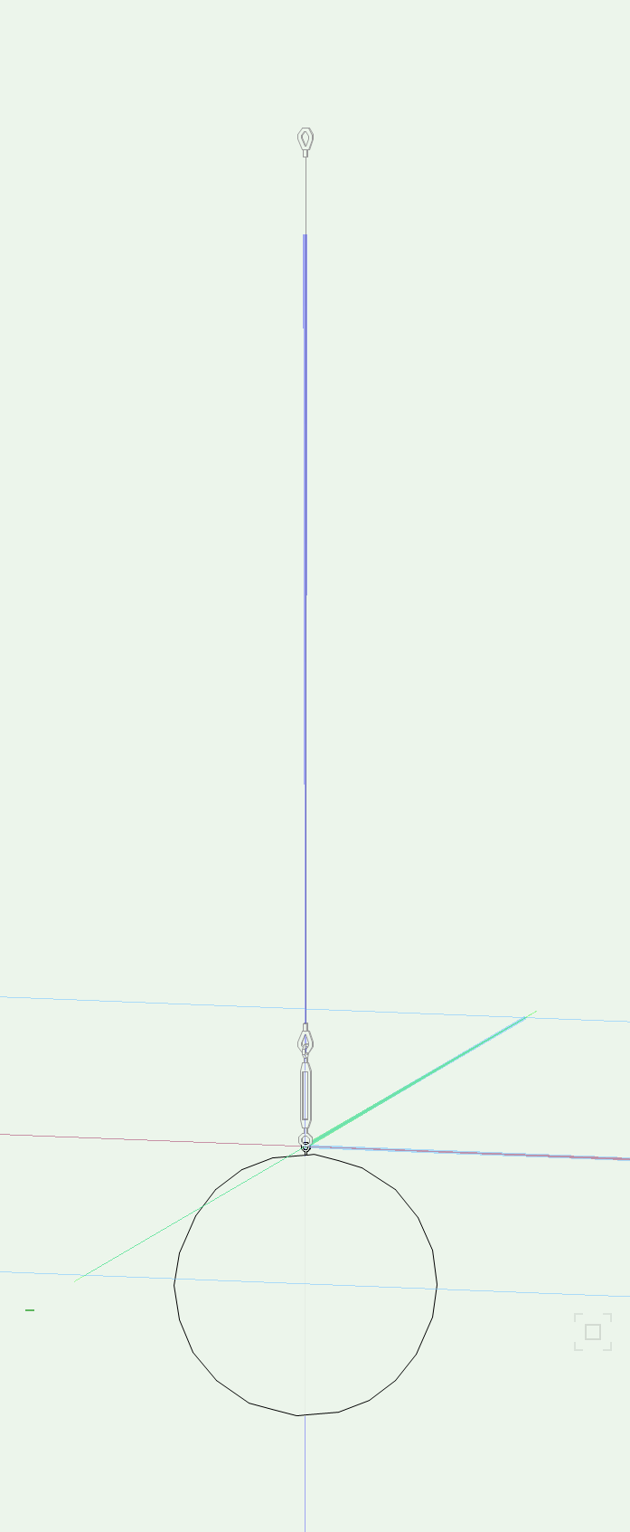
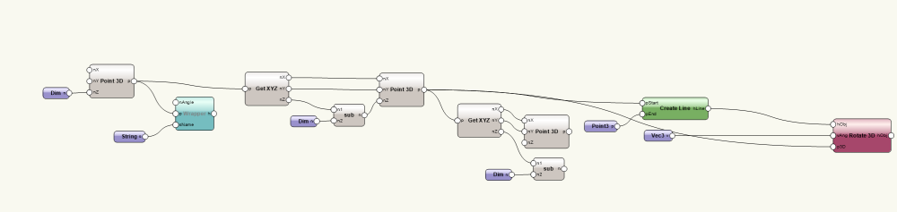
Hi All, Hoping to get some help putting together a marionette system for an adjustable mirror ball with rigging. My current set up is symbols for the mirror balls of varying sizes, a symbol for the rotator, and a stinger group made up of 2 extruded objects and a 2D line rotated vertically. This allows me to adjust the 2D line easily to adjust the height of the mirror ball (or anything else hung by a stinger). I'm automating this process into a marionette sequence to allow me to select the mirror ball size and adjust the stinger in 6" increments. The main issue I'm having is I can't seem to find a way to create or rotate a 2D line so that it is aligned to the Z-Axis. Rotate 3D doesn't work, and the create line command doesn't take 3D points. Is there any way to set this up in marionettes without converting the cable part of the stinger to a 3D extrude or polygon? Current marionette sequence is below:
-
@Marissa FarrellThanks! This node works great. Can you provide me the internal bug tracking number? I like to notate any bugs I run into so I can quickly check them when new service packs are released.
-
Hey @Marissa Farrell, I've attached the file I've been working off of - it has two main marionette scripts, and both are having the same layering issue. Thanks! Marionetting.vwx
-
This bug seems to be where the issue is stemming from actually. The components of the FOH symbol are all in classes like "Staging-Steel Deck" or "Staging-Pipe" and the layer I'm trying to apply them to is called 'Staging.' When I switch the set layer to Lighting, Structure, etc the node works fine. (Oddly enough, it won't set the layer to "Audio" either, but it will do all of my other standard layers.) Thanks for the insight here! Have you found any workaround to this bug?
-
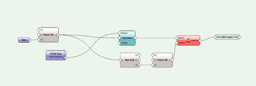
Hi All, I've been having some inconsistencies with the 'Set Layer' command that I've been trying to sort out. I have a few marionette scripts set up to automatically build and place lighting FOH setups, placing platforms, and then placing lighting consoles and media servers based on dropdown commands in the OIP. For the lighting consoles, I have had no problem getting them onto my 'lighting' layer, though I've had to place the 'Set Layer' node before any modifications (rotate, move etc). However, for the FOH Symbol (a library symbol made up of several different symbols for stairs, deck, legs, etc), the symbol will not take the layer command, no matter where in the sequence it is placed. I've had similar issues with another marionette script I have built to build stages - the set layer command does not seem to work anywhere I place it in the sequence. Is this the correct usage of the command, and are there any workarounds to make this command work properly? Thanks in advance!
-
3D Conversion Detail Per Viewport
Alex Talbot posted a question in Wishlist - Feature and Content Requests
I would love to have the ability to manipulate 3D Conversion Resolution on a viewport by viewport basis, as opposed to globally setting it up for the whole document. Almost always, I need higher resolution 3D conversion for certain viewports with prominent curves in them, but don't need them for all viewports. This would hugely help local and cloud publishing speed for drawings.- 1 reply
-
- 1
-

-
I use cloud services a lot to publish hidden line documents to PDF, which prevents my computer from being locked up with a publishing job for a while. It would be great to have the option to export as DWG on cloud services, as I do this often and it often can take 10+ minutes to export a Vectorworks document as a DWG.
-
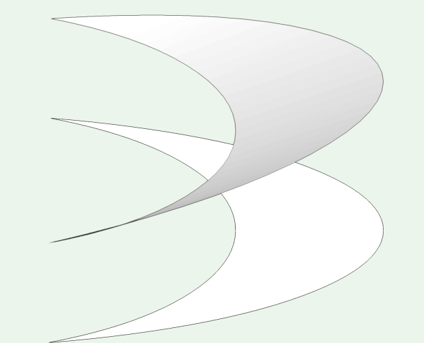
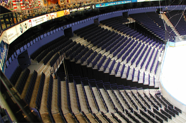
I'm attempting to draw the raked edge/seating section of a circular/oval arena, and have run into trouble getting the surface to make a clean extrude with the Vectorworks 3D model toolset. The top surface in the attached image is a drawn NURBS curve that has been converted into a solid, and the bottom piece is a NURBS curve converted into a 2D Polygon. Both objects are able to extrude, but I haven't found a clean way to combine/extrude them both to replicate the 3D object I'm trying to draw. Is there a VWX tool I'm missing that can do this easily? I've already tried multiple different 'subtract/add solid' methods, and haven't achieved what I'm going for.
-
Making a symbol count twice in worksheets?
Alex Talbot replied to Alex Talbot's topic in General Discussion
Thanks - the latter suggestion here seems like it will work. Is the proper syntax for calling a record field into a worksheet "RecordName.Fieldname" ? When I input it like that it isn't calling the value like I expect it to. -
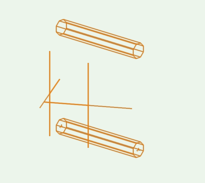
My base Vectorworks file automatically counts symbols used and complies them into a worksheet based on their record format. Recently, I've run into an issue with angled truss link bars/gates. These symbols are drawn with 2 bars in the symbol to make it easier to draw (I've attached an image to clarify). Rental shops, however, count these items individually, so it causes confusion when we send equipment lists to vendors, as our list shows half as many link bars as we actually need. Is there an easy way to make these symbols count double, either in the record format or in the worksheet?
-
Apologies if this has been asked elsewhere on this board. I'm building a marionette script to build platform systems and other complex structures from existing symbols. When symbols are placed, I can move them on the XY, but not the Z axis, even when I input 3D points into the symbol marionette. Is there an easy way to place symbols at a Z height, or move them on the Z-Axis through existing marionette plugins?
-
Once again I'm diving into using marionette tools to speed up my drawing process. I'm looking to build a marionette sequence that can build drawing labels as opposed to using the stock drawing label. Optimally I'd like the tool to be able to: -Pull the drawing title from the viewport -Pull the current view (Top/Front/Side etc) from the Viewport -Pull the scale from the viewport -Fill in the drawing # in the OIP -Place and rotate an arrow symbol indicating the upstage direction Has anyone tackled something like this before? It doesn't seem immediately easy to build something like this with the stock marionette toolset.
-
Marionette to get a list of symbol names from a folder?
Alex Talbot replied to Alex Talbot's topic in Marionette
@Antonio LandsbergerThanks! This is a really helpful plugin. -
I'm building a marionette plugin to automatically build platforms from predefined platform leg and deck symbols, and have run into some trouble sorting out symbol selection for the plugin. Optimally, I'd like to populate a dropdown from a list of symbols in a certain folder - if our legs are in one folder, the plugin could pull all of those symbols into a dropdown in the OIP. If this is not possible, I'd also be open to a dropdown of strings corresponding to our symbol library. Are either of these possible with the existing marionette toolkit? I've found mixed information on dropdown lists for strings.
-
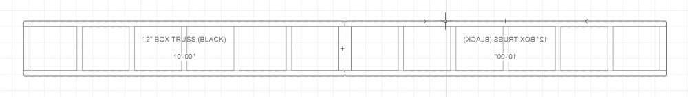
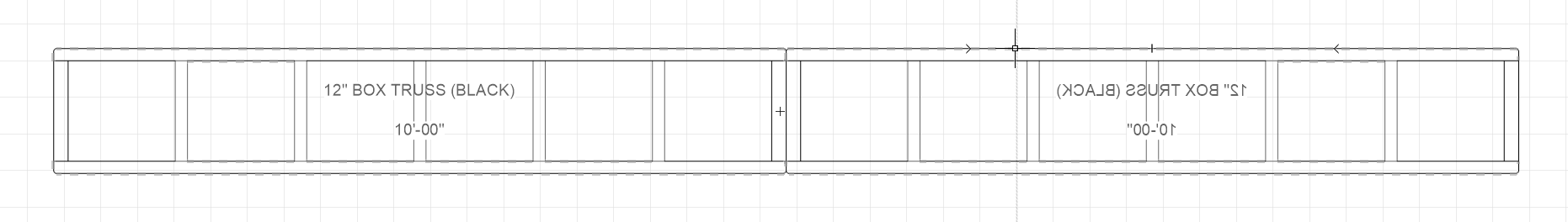
I have a series of 3D truss symbols for different lengths and styles of truss, and recently I've started adding 2D Top, Front and Side views to these symbols to make my drafting a bit cleaner. I often draw by mirroring large sections of truss, and I've found that labels (specifically data tags with the truss name and length) in the 2D symbols flip themselves if I mirror the truss objects when I draw them. Playing with the 'adjust flipped text' settings seems to do nothing to change how the text renders. Besides changing how I draw truss layouts, is there any easy way to keep this text oriented in one direction when I mirror truss objects?