


ddcpe
-
Posts
72 -
Joined
-
Last visited
Content Type
Profiles
Forums
Events
Articles
Marionette
Store
Everything posted by ddcpe
-
Thanks Tom. I think I realized it after a bit. It was really confusing as I just assumed there would be some sort of basis for a wall by default. When you first open the wall tool it seems to have some settings even though it had not been used. That's what I mean by default. That's also what is confusing about a tab that says "Convert to Unstyled". It just seems by the wording that it would wipe out the settings and go back to whatever unstyled is when the tool is first opened and before any changes to its parameters have occurred.
-
How do you rotate an object to a specified pitch rather than degree/radian... for example you have extruded a 1.5" x 11.25" rectangle to around 15'. You then get a face view of it and choose the rotate tool and snap to the bottom left corner then grab it out along the bottom edge then rotate it up. How do you make that rotation be 6v:12h rather than pulling out a calculator and finding the inverse tangent of 6/12 in degrees then specifying that. Seems like a stupid way to do it but its all I can figure out. Thought I saw a video somewhere of this being done but I can't remember and a search gets me nowhere quick.
-
So the door leaf is on the NONE class. I placed the doors on another class and it seems as though the jambs take the active class but the leaf and swing and whatever else stays in the NONE class. I guess its all in the Symbol properties which its going to take a bunch of time to figure out. Seems like one should be able to quickly set all the parts of the symbol to take the active class when inserted. probably a way but I haven't figured it out.
-
Was working along with doors in my model and all of a sudden out of nowhere the 2d plan view changed and the opened door leaf with swing is gone and only the jamb shows. How the hell did I turn it off and where in the name of god do you toggle it back on? This is the most frustrating tool so far in VW. Nothing but a giant pain in the ass.
-
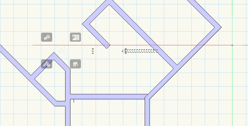
Trying to insert a pocket door in a wall but the handle (insertion point?) is off to the left about the width of the leaf. Any idea why? Can't see anywhere to set that distance. Seems absolutely stupid that it functions this way. Though the screen snip doesn't show it the handle is in that faint box surrounded by the four little greyed out icons. Those only appeared when I did the snip. When working with the door its a little black cross and is where my cursor is.
-
In addition to above I just realized when I draw a wall on the upper layer with active class wall 2 the wall has the wall 1 attributes and is also in class wall 1 according to the OIP. Weird! Seems pointless to have a tool that tells you that you are changing the wall attributes to be by class but they don't do what the words say.
-
I created a wall type from a simple standard wall called WallStyle-1. I created and saved it while working on a design layer with elevation 0' and a class called "wall 1". I also have another class called "wall 2". The two classes are basically the same but with different fill properties. I have another layer with elevation 8'11". If I activate the wall tool and use the Preferences tool I see under Edit Wall Preferences that the attributes are set to "by class". Now when on the upper layer and with wall 2 the active class if I draw a wall it draws at the correct elevation but it fill attributes are by the wall 1 class even though its not the active class. Any idea what's going on? Shouldn't the preferences if chosen by class apply the active calss properties?
-
I started creating walls by opening the wall tool. I then modified it by clicking the little tool icon and changing the thickness and the Height and such via the "Insertion Options" tab. I proceeded to draw a bunch of walls and insert doors, windows, etc. Somehow or another I accidently chose a different wall style from the drop down list. Now for the life of me I cannot figure out how to get the wall tool to open back up with the previous wall type. Along the way of trying to get rid of the wrongly chosen wall type I opened the Wall Preferences page for the wrong wall and clicked "convert to unstyled". Did that change the default "unstyled"? Where on earth is the default? If I click on the wall I first used that is what I want, then in the OI palette it says Style: unstyled, and Type: standard. But I can't find this anywhere and can't get back to it. Jesus this is unnecessarily convoluted.
-
How do you create a simple uncased opening in a wall? Been looking for hours and can't find a solution. Attached is a simple example of what I want. In front view on the left you can see the polygon I want to carve through the wall and have uncased edges. On the right I used a plain door modified and saved in my RB as "opening". My work around seems really kludgy but maybe that's all there is. Basically its this shape cut out of a wood framed gyp brd wall with gyp brd finished edges. I'm pretty sure I saw a video of someone doing this but I cant find it. Also, my door and window options in VW library in RB don't have an option of for a plain opening. I had to choose a flush swinging door then modify it to uncased opening to get the plain opening. I then used the interactive mode to place the two openings so they touched to appear as one. uncased opening.vwx
-
I was thinking that might be it. Weird extraneous stuff that wont go away. My graphics cards are pretty new and robust, memory is more than adequate so any clue why this would occur?
-
I can't select it. I created a new design layer then deleted the DL it was created on but it popped over to the new DL. test.vwx
-
Option 1 is exactly what I want to do; thanks a bunch. BTW, any idea how to get rid of the extraneous line work left over from an abandoned attempt at farting with subD tool? I did a cube, fiddled with it, then selected it and hit delete on the keyboard. The shaded solid went bye bye but the lines of the edges remained and cannot be selected, deleted, altered...they are just stuck there. All classes & layers are set to show,snap,modify but these lines seem to be in some hidden space I can't access. Any ideas what is going on? Seems my only alternative is to delete the document and staart over. I must be missing something but have no clue what it is.
-
I'm doing some preliminary modeling of a roof form. What I would like to do is draw a rectangle of the are the roof covers then be able to drag one of the corner vertices up vertically to create a crease from corner to corner. I can not for the life of me figure out what tool will do this. I tried using subdivision but that was a mess. With that tool I started with a cube primative added a corner to corner edge then pulled a corner vertex connected to the edge I added up and kind of got what I want. Not to mention that there seems to be no way to select the line work created by altering the primative. I selected it and hit delete and the cube went away but the distorted edges are still there and there is no way to select them. All the class and layers are visible and set to show/snap/modify but to no avail. How do I get rid of the detritus? Anyway, it seems like a kludgy way to do the task. I was hoping to be able to make a rectangle add the diagonal then pull up that corner and simply get two plans intersecting along the diagonal. I think this can be done with sketchup.
-
I downloaded some SAT, 3D files from Simpson into a class with fille properties. The objects wont fill with anything but the NONE fill properties no matter waht I do. I can go over to the Attributes menu and select the fill color I want and it works just fine but if I change the Attributes to be by class it doesn't change to the class fill properties chosen. Any ideas why?
-
Yep to both replies. Seems the only decent solution is to draw the vector and dup along path at set distance then erase the vector. I seem to remember a video of somebody doing what I wanted without the step of drawing the vector. The vector was assumed by the first and second click so no line to erase. But maybe I'm just hallucinating. BTW, I noticed that when using the DAP tool that when I select a combination of the center...tangent...keep... buttons and select preview then select another combination of the buttons the preview disappears but pressing the preview button no longer gives a preview. The preview seems to only work for one combination and the only way to get a preview of another combination is to cancel and start again. IS that a bug? Suer seems like one to me. Not much point in having a preview that only works for one combination.
-
I have an object that i want to copy at a set interval along a given vector. Note that the vector is on a principle plane but oblique to a principle axis. I don't want to take the time to calculate the number of duplicates to fill the vector. I want to be able to select the object, set the spacing and click the end point to specify the vector. I don't have a line to select that defines the vector (path object) so I can't use Duplicate Along Path. I was thinking Move By Points would work but it wants to distribute items evenly between points, or you have to specify the number of duplicates you want along a path at a fixed distance. The trouble there is you have to spend time and effort figuring out how many fit between the start and finish. There must be a simple way to do this but I can't figure it out or find it in help. Attached is a file with 2-2x4 extrudes similar to a double top plate assembly. Typically these stitched together with nails at some specified spacing to create a chord or drag member in a diaphragm assembly. There are many similar conditions where I like to make a pretty picture of the assembly for particular situations just to make it abundantly clear how the parts go together. So, that's my dilemma. How do I accomplish this task without doing any math; just select, specify distance, and select direction/vector? Thanks, move by points.vwx
-
is there any tool set that has nails as fasteners? Its the most common fastener out there yet doesn't seem to be in VW for some reason. Would be a nice addition. My work-around has been to use a sheet metal screw with a pan-head and square slot and it happens to have sizes that are similar to nails...#8, #10... Not quite right but it something.
-
Is there a way to have the header at the top of a tool set say the name of the tool set instead of just "TOOL SET"? this is the "3D Modeling" tool set but it doesn't say anything but Tool Set. Kind of silly. It would be helpful to have the name in the interim till one can remember what the icon represents. Personally I have always had a hard time with icons. I have always had difficulty figuring out what they are supposed to represent. So for me words are really helpful.

-
Thanks so much for all this info. I really appreciate it.
-
Yeah, I kind of figured as much but can you see how valuable it would be to have some sort of bounding box for something as complex as a vehicle so it can easily be moved around? It makes no sense to me that a 3d object as complex as this does not have a snap point integrated that is, for example at the center bottom of the object so it can be placed accurately. How do you move something like this around and set in accurately on a driveway that has compound slopes? What matters when sizing a parking area or garage are the extents of the vehicle hence the utility of a bounding box.
-
this seems to be a consistent problem with 3d symbols. I inserted one of the legacy 3d people (Male 15) and the same problem of no handle anywhere to move it around. I must have some setting wrong but I am at a loss for what it might be.
-
BTW that's not the insertion point its an intersection of the underlying mesh. There are butt loads of them if you switch too wireframe. What I would assume something like this would have is a bounding box like grouped objects with snapping points at the corners and centers of the lines that make the box.
-
I just grouped the symbol and it still has no useful snapping properties. It has a bounding box but I can't get a snap at the corners to move it. I get the double sided arrow to deform it but not the cross to grab it and move it around. I must have something set wrong but I don't see what. Its stupid that an object like this can't be drug around without so much screwing around.
-
the symbol has a bounding box. Why doesn't the cursor snap to the corners of the box? Does it have to be turned into a group for that to work. It seems really clunky to have to add insertion points to something like this. It should automatically have them at the four corners and center in top view. I tried adding the locus but it didn't work. Don't see how you did that.
-
There doesn't seem to be any sort of insertion point for the symbol. It's bounding box has no no snapping points. Is there a setting to turn those on?
