

JuanCarlos
-
Posts
123 -
Joined
-
Last visited
Content Type
Profiles
Forums
Events
Articles
Marionette
Store
Posts posted by JuanCarlos
-
-
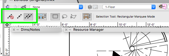
I would recommend using the same Railing Fence Tool in the second mode in the Tool Bar
HTH

-
 2
2
-
-
I assuming that something like this is what you are looking for.
You may need to play around to get the exact modulus
HTH
-
Very good!
Bounces= 3 all settings to Low - No Textures - light source just the heliodon - Foreground = Hidden line Careful
-
1
-
-
Tic Tac Tic Tac
-
 2
2
-
-
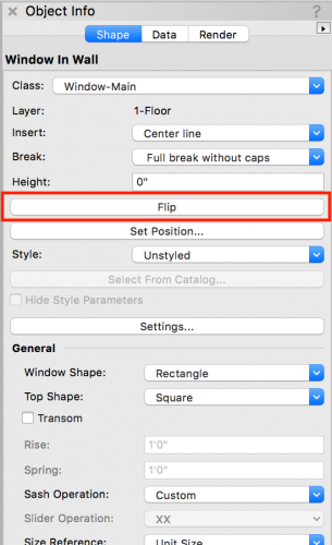
Select the window(s) and flip them with the button in the OIP
HTH
-
I do concur with Tom, and if there is no issues on renumbering in DD and/or CD I would still update them, the clip shows the technic I would use
HTH
-
1
-
-
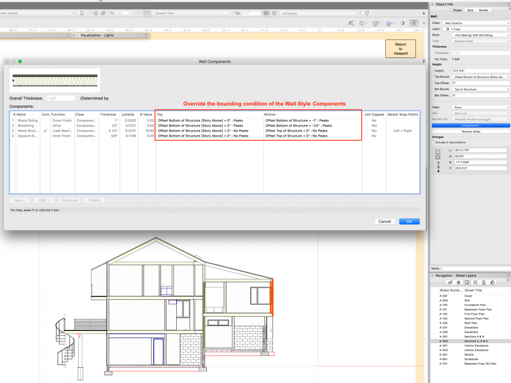
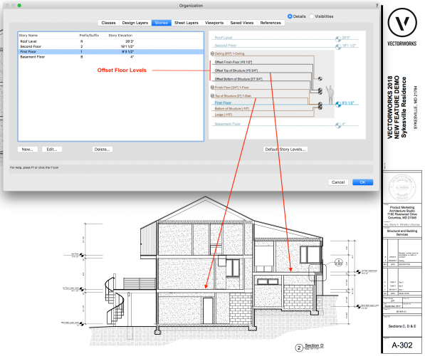
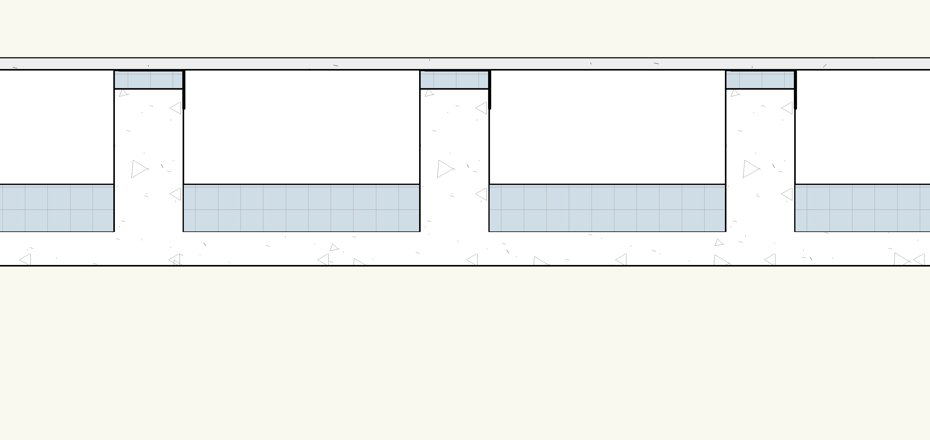
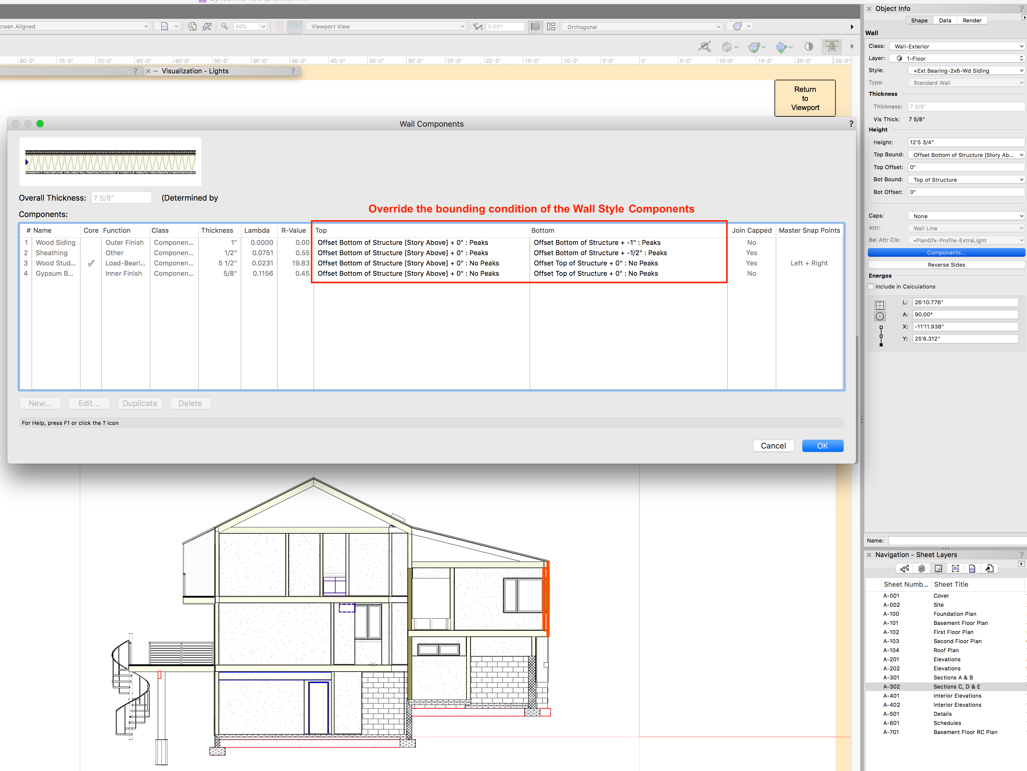
As of Vw 2018 a new feature has been added that may help this situations, now the component of a Wall Style can be overwritten. See attached screenshots for Story setup and Wall style overwritten
HTH
-
There is a document in the Vectorworks web page that can help you
http://www.vectorworks.net/bim > How > Training > Get Started > Model Setup Tutorial
or direct download http://download2cf.nemetschek.net/bim/model-setup-tutorial1490810240.zip
HTH
-
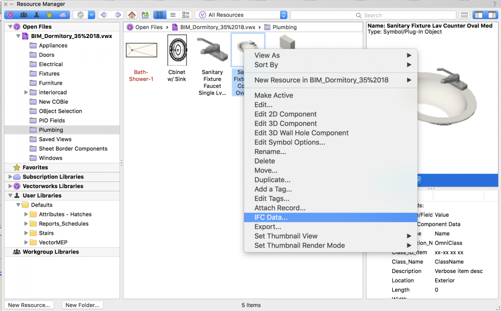
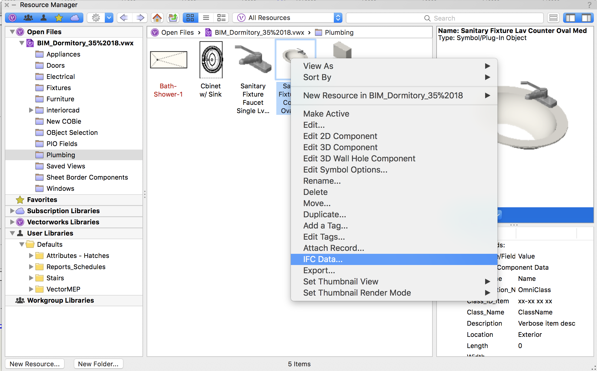
For Symbols attach the Ifc entity directly to the symbol through the Resource Manager
HTH
-
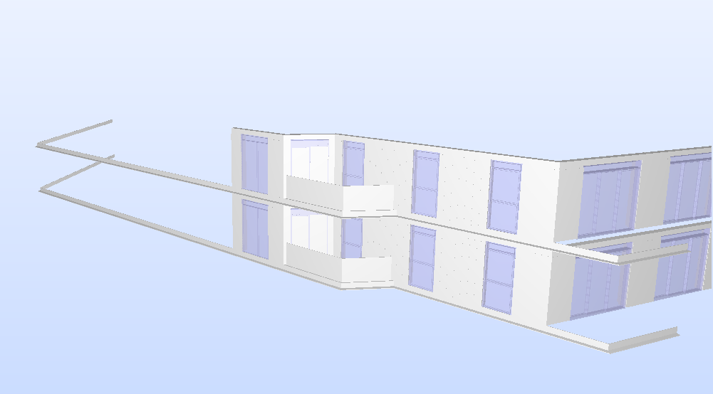
For the dislocated objects, attach the Ifc entity before you group them, if you have multiple objects with different Ifc entities use from the AEC dropdown menu "IFC Zones, Systems and Groups..." to create any of these.
As for the windows, the window is there, the frame cuts the wall the glass doesn't, reinserting it and flipping it some times fixes it, I will write a bug for it.
HTH

-
Have to ask – Are all windows inserted in walls?
If yes, could you send me a file with the wall and windows you are showing, for testing.
Thank you
-
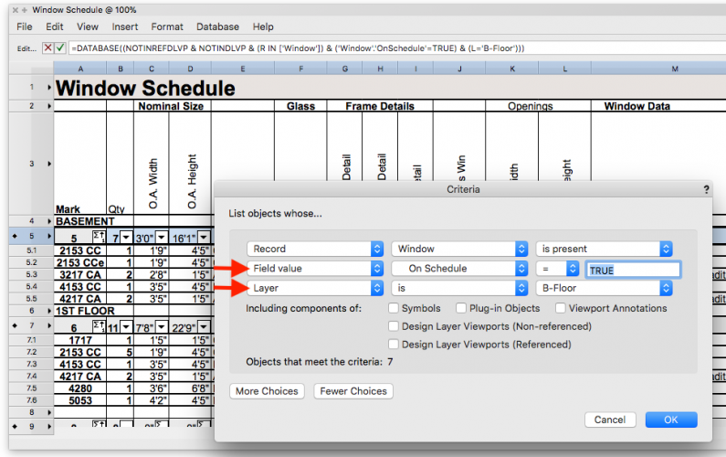
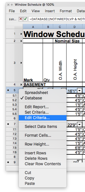
Edit the Criteria to fit your needs
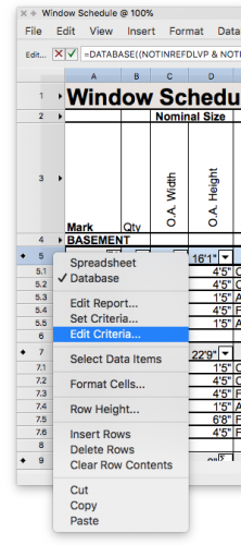
-
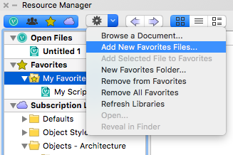
Would Favorites work for you?
HTH
JC

-
Have you tried using the Resource Manager Favorites?
HTH
JC
-
-
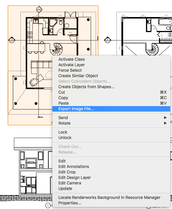
If something like in the picture bellow works for you, it can be added through the Workspace Editor to the Object Context Menu Folder.
HTH
JC
-
1
-
-
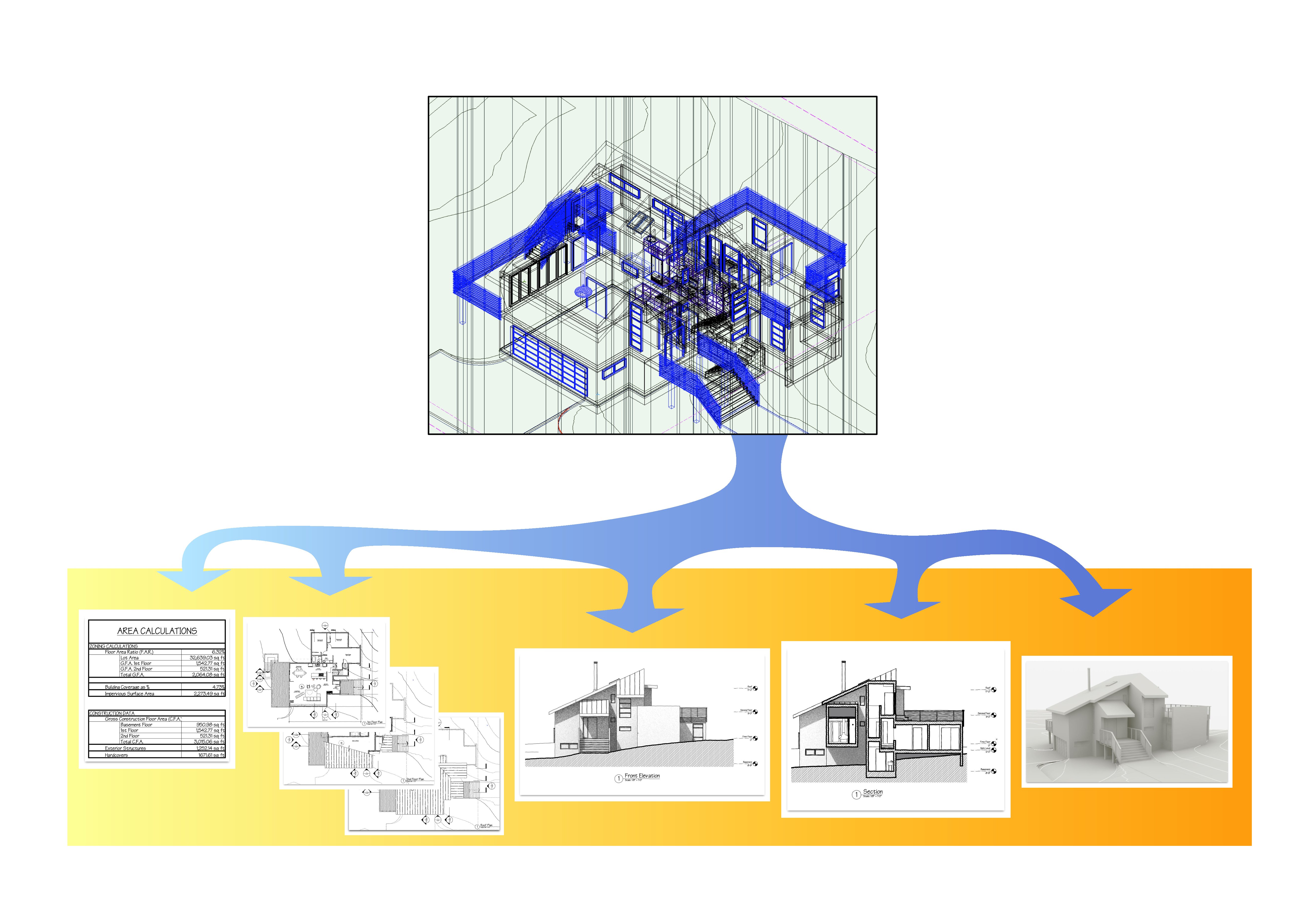
I totally understand, I also like to draw things one time and expect them to be graphically correct in all my plans, here is my work flow;
Rules:
1.) For all objects make all attributes “By Class”
2.) There is no rule that says Stack Viewports Not Allowed.Viewport possibilities: for Layers; On/Off/Grayed, alter staking order, for Classes; On/Off/Grayed, Override Class attributes (this will only be possible if you comply with rule #1.)
Some times there are several objects with the same class in different layers and there is a graphical need for some of them that are in a different layer to be represented differently, Divide and Conquer, you can stack viewports (rule #2), yes there will be some initial setup, however it will payoff when you modify things.Sample bellow: a simple roof that traverses two floors, all objects have only been drawn once.
1st floor has a stack VP for the 2nd Slab with a class override
2nd floor has stack Vp's for the roofs with class overrides
Roof has Layer stacking order and class overrides
HTH
JC
.jpg.4e3f4173c8e2b9082c9511c4bfa97261.jpg)
-
1
-
-
Would Class Override in Viewports work for you?
-
1
-
-
Here is another idea;
Do the same Wall Style as Jim Smith and set the Wall class pen attribute to none and follow steps bellow
-
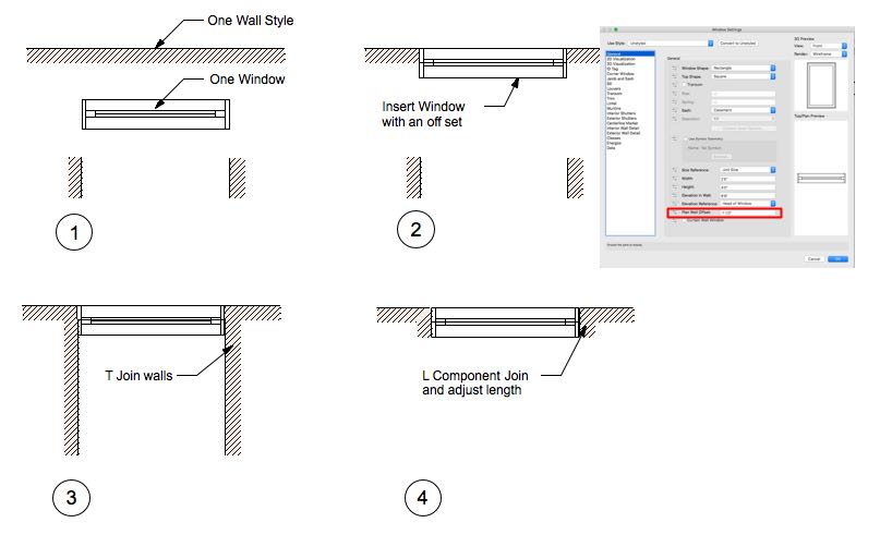
A referenced DLVP is a container just like a Symbol, currently Vw does not have Styled Symbols and a direct connexion like the one you described is not possible, however if your interest is just a graphical appearance here is one way of doing it;
1.) Have the Unit join all the walls to the exterior and party walls as you would like to see them
2.) Select all the interior walls > Group > Convert to Symbol.
3.) Use Symbol for the units, if used in front of exterior walls the unit internal wall will appear to be cutting the exterior walls.
Hope this helps
JC
-
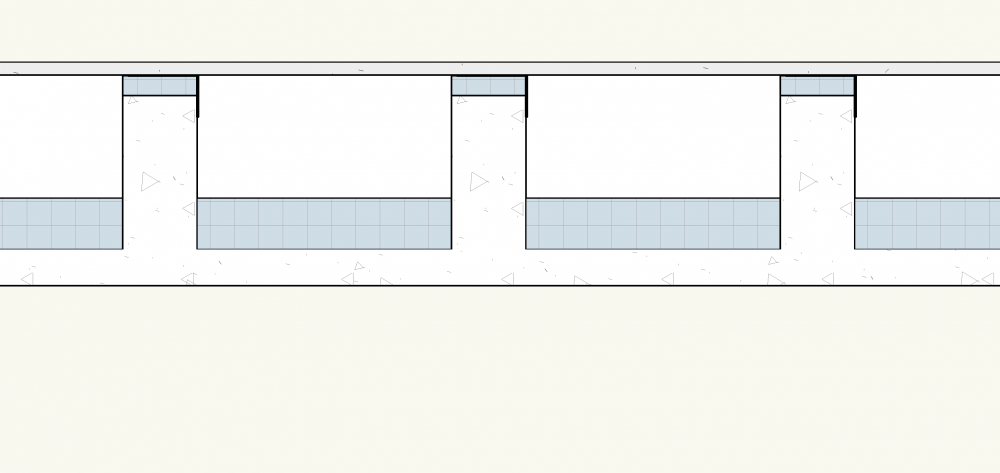
Currently the best way to approach the issue is to have a wall style with all the components you normally use or are common to your area saved to your office standard folder (All Components WS), then any time you need a new wall style you can duplicate the All Components wall style and delete the unused components since it is easier to delete a component than to create a component.
Hope this helps!
JC
-
2
-
-
"One issue I did have with the FBX model being imported were you could see through the back of some wall so you needed to set up the file correctly"
Alan, when this happens reverse the normals
-
Have you tried to set classes to the different components and for the top/plan view override the attribute fill to none of the handrail class
-
Will
Go to File>Export>Export IFC Project... From the dialog box select Data>Export Options and then select "COBie/Facilities Management" from the Model View: dropdown menu. Don't forget to do the Layer Mapping before you select OK.
You will have then an Ifc file, if you want to see this file in spread sheet form you would have to install the COBie Tool Kit.
Hope this helps


Stair down label
in Architecture
Posted
There should be a blue handle, click and drag
HTH