richard2020
-
Posts
30 -
Joined
-
Last visited
-
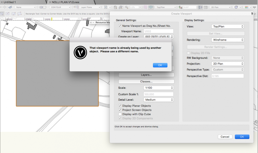
The only way I could get it to work was by unchecking the 'name viewport as DWG / SHT number' and giving it a new name, which I've never had to do before.
-
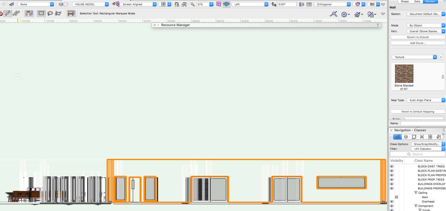
The orange border in my case is the box I used to crop to. Can you please advise? Thanks
-
Hi there, I'm trying to show the walls with brick below half height, above that a horizontal board rail and vertical board above with a thick coping overhanging at the top. I'm guessing this is a wall stye amend but is it just a case of stacking components on top of each other on the same plane? The finish output is just 2d line and infill no colour. Any suggestions on how to do this please? Thanks
-
To be honest I'll settle for now on how to create a pad in the exact location through being able to see through a site plan to the underneath buildings. Any ideas on that? Thanks
-
What I am looking for is, somewhat unsurprisingly, to model a development, set it in its scene and give nice visuals to clients and to support planning and maybe some technical take-offs for contractors but that's a nice to have. Surely the same as everyone else's goal using architect? Could there be another achievement target for anyone using architect? I don't have a set workflow. After 8 days of this trial and probably 8 hours a day, thousands of searches, dozens of hours of tutorials, I am not sure now is the time to be discussing workflow. I take it there isn't a simple answer to the questions. If it starts with 'you don't want to start from here' I'll revert to my position of days ago in re window. As an update, I tried deleting the pad, and it appeared to delete yet on update the recess is still there. So I am not in the position where after a week of evaluation, and hard core effort as you'll have seen I have to turn up to work tomorrow and tell the boss that actually I still don't have a single worked up model for him to assess. That's going to be awkward for me. So I'd rather an answer now to these 3 questions if possible. I had to get this finished by 9 am Monday and I'm not going to - not for lack of time or effort.
-
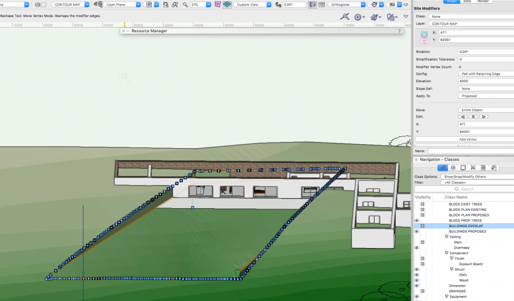
Hi again. I've hit another wall. Hoping someone can help. As the next step in this discovery phase on vectorworks, I need to set the building on it's site. So we now finally have an actual building. Rather than risk corrupting that file, I've created a separate site model document. Following the tutorial which was great I managed to build and contour the site, although it didn't fill in up to the edge of the site. Stopped at the last contour. But I can live with that. After much trial and error and rewind of the tutorial I managed to insert a flat pad as a site modifier. Question 1 - With the site plan built, how can you trace the outline needed for the site modifier pad? The site modifier pad needs to be tight to the building. I couldn't find any settings that et me see the tracing pad below? I need to get the pad in the right place and I can't see how, or find any tutorial on this? Question 2 - Assuming that someone can help with the location of the site modifier in Q1, I have tried every type of pad for hours. Retaining, non retaining, I've tried varying elevations. But in every case it maintains the 'flat' of the pad and recesses where the contours are higher, which is cool and as we want, but where the pad crosses over contours that are lower than the pad it builds up the ground. In this case the property is on the side of a hill so we need to level it off and recess it where the contours are higher but not change the contours that are lower. That is just the view. Any ideas on how to do this? Question 3 - All of this journey has been about trying to build a model as part of our architectural design to see if this tool is for us as a practice. So if I can get help on Q1 and Q2, so that I can let a pad in to the right place accurately, without building up where the contour is lower then we are ready to place the building into the pad location. I haven't been able to find any help or tutorial that addresses this point. I tried so many approaches but the only thing I've been able to get to work is to create a contour layer, elevate it lower than the buildings so the finish level of the pad reflects the finish floor level of the building.It works but its probably the wrong way to do it. Any suggestions on the right way? Both question 1 and 3 relate to location of site pads. I guess theoretically if I could reshape the pad so that it was the right shape by dragging vertex but as you can see there are thousands. Not only that moving them would go across different heights too. When I tried dragging the whole thing messed up. I could possibly use the same approach if it worked to trim the pad to where the contour becomes lower but this just isn't feasible with this number of vertex. Any help gratefully appreciated. Thanks
-
Ok everyone - final update - the final setting was that even though I had set the model to open GL, when I had made all the other changes it had gone back to wireframe. So actually with the suggestions Tamsin had made it was working, but the render was set to wireframe. I must have changed it back when I was trying everything yet in the copy I made for Tamsin it had reverted to open GL so all seemed to work there. So in summary to get white background for walls suitable for elevations if you have components in walls then: 1) Style fill set to solid through resource manager 2) Class fill set to solid through tools -> organisation - > classes 3) Render set to open GL through view -> rendering.
-
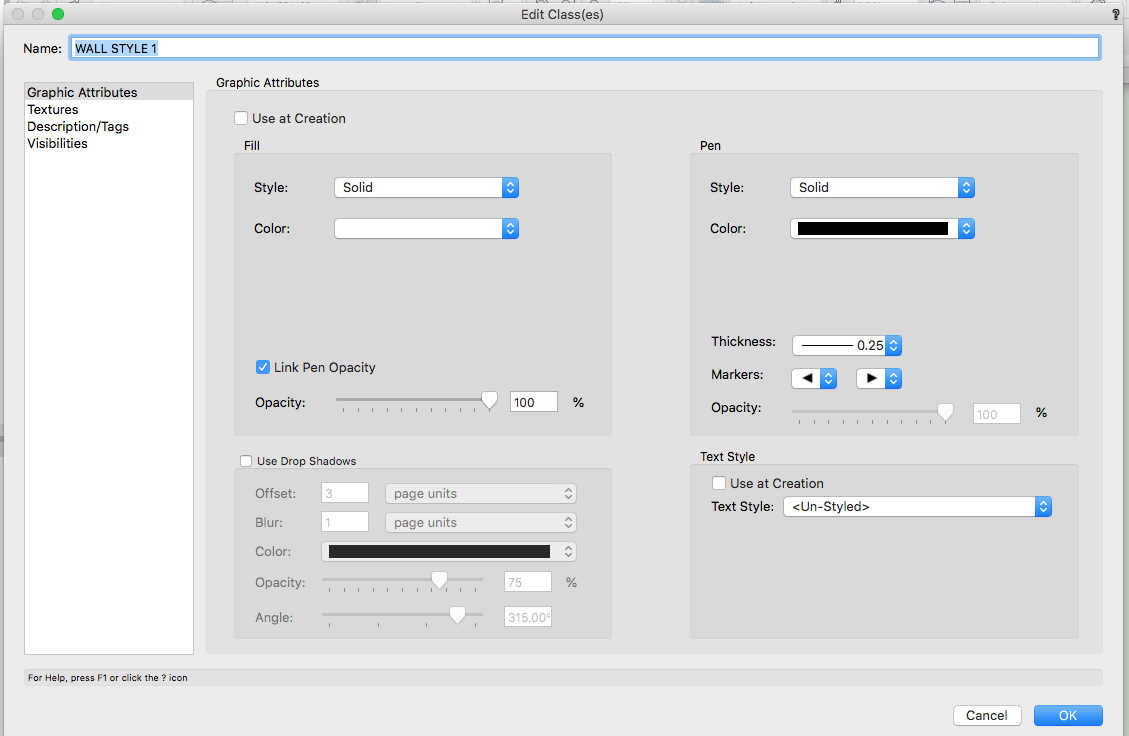
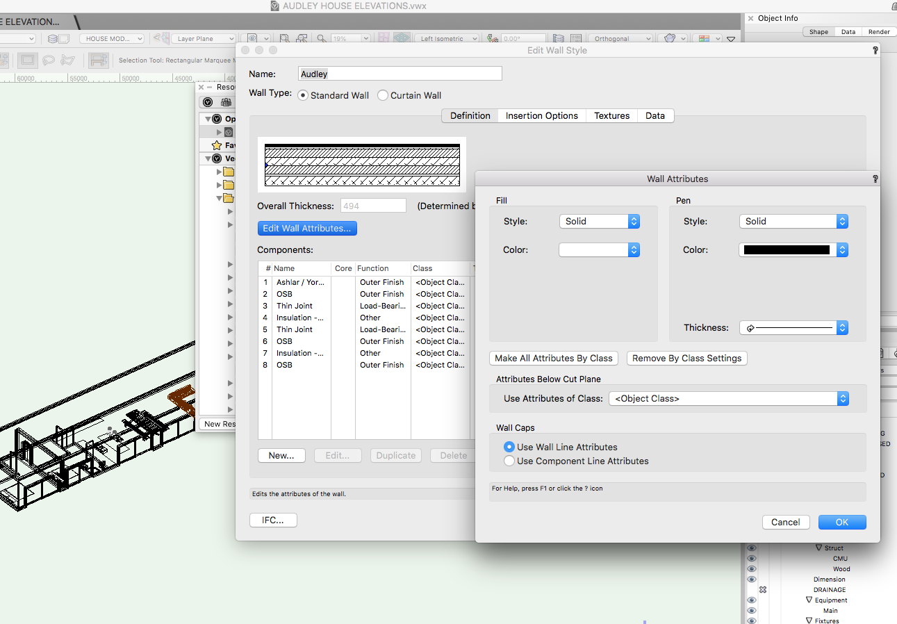
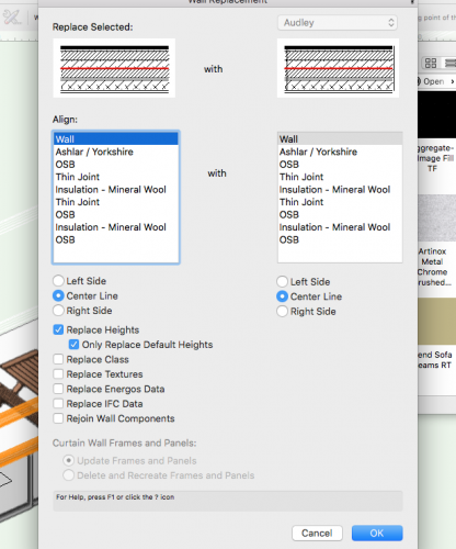
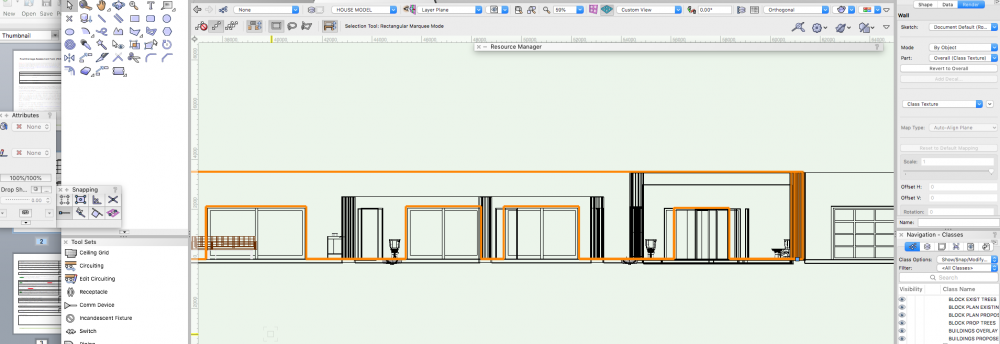
Actually I spoke too soon. It worked brilliantly in the dummy copied version I stripped out, but then when I applied it to the main model no joy. Still no visible walls. What I have in the model is as follows: The walls in question are in class Wall Style 1. Wall style 1 as per attached pic has class set to fill colour white. So thats as it should be I think. Within the style, I have selected the style in resource manager, right clicked it, clicked edit, then clicked edit wall attributes, and as per screenshot, the fill is set to solid. Yet still no walls. It worked fine in the dummy file. So there must be something else here too. Any help gratefully received. Thanks


-
Hi Tamsin, Thank you so much for your help on a saturday. It worked perfectly. Thank you very much!
-
Here it is then. Thanks. tamsin.vwx
-
I'd rather not send the file. I wouldn't be comfortable uploading it here, and I don't use dropbox only we transfer. Where else are there settings? It seems so complex just trying to make a wall.
-
If I am using a wall style it is unintentional. For now after 3 hours I'd settle for showing a white wall. I'd prefer a texture, but a white wall would be significant progress! Thinking about it, wall is made up of components, so yes - I did put components in it so my comment above isn't right. When I made them I did set the components to each have an image - hatching or similar. I created a new style for it. I've attached a screenshot of the style. Thanks
-
Hi Tamsin, Thanks for helping. In terms of wall style, I just followed what the BIM section of the university said. I've since tried my best but the screenshot above I think shows all of the settings on this wall. To the left is the attributes tab showing fill greyed out. To the right shows the OIB with class texture set. Is there somewhere else I should be looking? In the tools -> organisations I have 4 wall classes, all of which are set to solid fill. The file is 36mb so may take a while ........
-
Hi Boh, Thanks for the reply. In all other objects I use the attributes box to set fill, but when I click on the wall the attributes are greyed out and set to none. So I can't change them there. Is there another setting somewhere that is relevant? Thanks
-
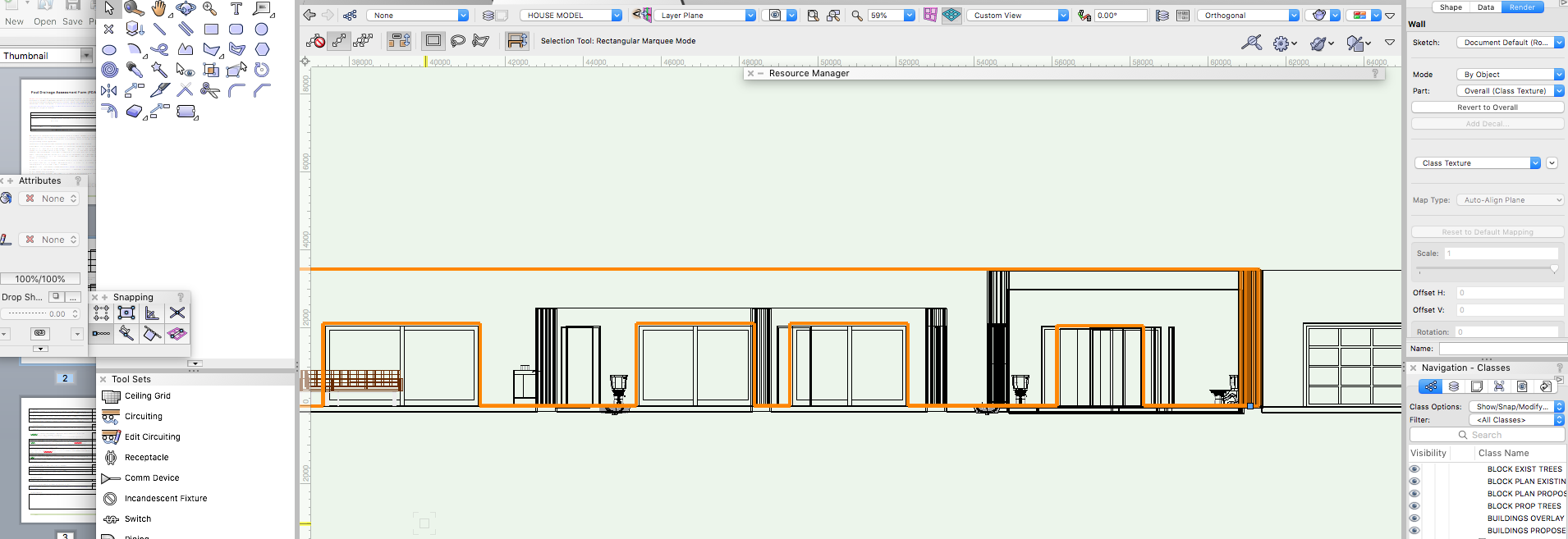
Hi there, I feel ridiculous asking this, but I can't get my walls to show with any fill or texture. I've tried for 2 hours before reaching out here, I've trawled the university and google, but to no avail. There are hundreds of posts on this, but none that seem applicable as far as I can understand it. Apologies if I've missed it, but if someone could hep i'd really appreciate it. As per diagram below, I have lots of external walls, but on a view all I can see is the edges, not the solid. I've tried tools -> organisation, choosing textures, I've tried render -> Open GL, and pretty much every other technique I can see. But my walls are stubbornly remaining just a collection of edges with no fill. I'm sure it's simple, but I just can't find it. Help gratefully received. Thanks