


Amber Hine
-
Posts
19 -
Joined
-
Last visited
Content Type
Profiles
Forums
Events
Articles
Marionette
Store
Posts posted by Amber Hine
-
-
Amazing, many thanks, I shall give that a go tomorrow. 🙂
-
Hiya,
File below.
I only seem to be able to make a section- also included in the file. The view (clip cube) I am looking for is saved as Section B back in the views for the project. Its probably something simple that I'm doing wrong, but I feel like I am following the steps... many shruggs...
https://www.dropbox.com/sh/00wo9xg052hu1bz/AAAIDrolK7etgCScooSHsQ5Ba?dl=0
-
man, you guys ran away with this- love it!- I shall have to take a further look at some of your alternative solutions at some point- nice! 😄
Thanks for being awesome 😄
-
 2
2
-
-
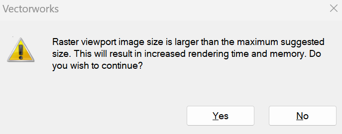
So I seem unable to create a viewport with a clip cube.... I am selecting a red face then right clicking and trying from the view menu, and I seem to be getting one of two things- something that looks like an empty viewport with just a viewport data tag, or something so large it can't render- it shouldn't be larger much than the sheet if it is properly following the the clip cube bounds- but I have too zoom out so far to see the viewports extents that I can't see the sheet outline anymore...
What am I doing wrong?
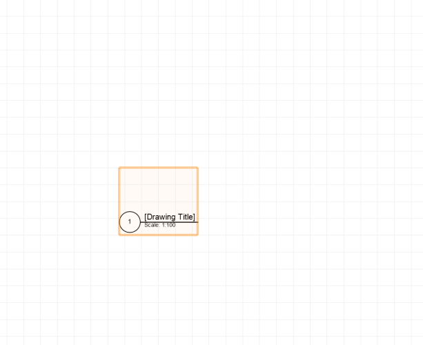
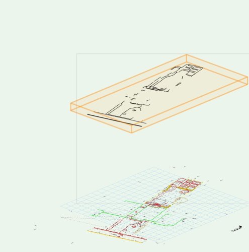
The site fits 1:5000 on A1 as a top plan view, I am trying to create a partial clip cube of the site @1:100.
It has multiple site models in it- could that be the problem- the section line tool seems happy to deal with it....
I have the shaded render mode selected.
When propmted- one of the two methods above asks, the other doesnt, I select display with clip cube...
it seems to work with a simple cube in a new file...
-
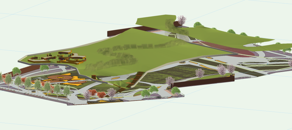
So Its essentially a roof park.
With this process I am trying to achieve a thickness to the top layer that isn't as deep as the site model skirt... say 30cm, ideally such that I can project up to from below with the shapes below that will form the vertical glass walls....
I don't know weather seeing the below may help... really it will be the projecting up that'll help with at this point- I have a facia now 🙂
-
On 8/25/2021 at 10:45 PM, jeff prince said:
I took a stab at it. The trick is to give your site model a skirt to use for developing the facia 🙂
Another trick, make a copy of the site model w/o a skirt to use as the roof surface for easier texture mapping.
Attached file has descriptions in the design layers for the steps I took. Hope it helps.

hmmm, not having much luck, I can't seem to create nurbs from the site model skirt... I get this message...
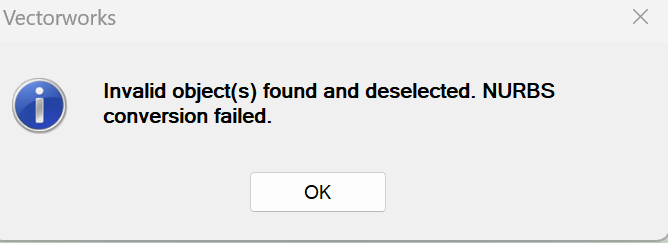
I have included my site model into the file above...
-
2 hours ago, jeff prince said:
@Amber Hine You know, a little more context might help with a better solution. How were these weird surfaces created initially? It reminds me of something generated from a site model.
If that's the case, you might enjoy this old trick....
Fabulous, this will be helping with my next bit- it was generated using a 3D poly and 3Dloci as a referance point, that were also used to make a site model- think you helped with that a little last week too 🙂 many thanks again 🙂
-
2
-
-
2 hours ago, VIRTUALENVIRONS said:
Jeff method is probably to the "go to" method, but I worked out another one because it's Saturday afternoon and raining here. I appears the surface follows NURBS math, so I Just picked off the top curve, dropped it and lofted the surface to make a fill. The file is included, but it has the weird joint shown above.
So that is exactly what I had been trying to achieve, but the loft tool kept failing- was it just because I missed the overlap- I feel like a right plonker! thank you!
-
1
-
-
It would certainly be nice to just shell it! 🤣
-
1
-
-
Having trouble lofting between the two NURBS in this file.
All I want to do is create a surface between them and then give it a thickness to create a roof top edge, It just for visualisation- So I have tried various methods to create this effect and I can't seem to get there... any ideas, hairbrained or otherwise would be appreciated...
https://www.dropbox.com/sh/gj0ugurf8om9bpm/AADPyhCoYk8BvihkHp3TeYHKa?dl=0
-
file added through dropbox
-
Well if pulling my hair out would help I would be bald....
I am trying to create a multilevel rooftop park with step access from ground level for rendering purposes mainly.
It has three different 'true levels' and then slopes in between those levels. The building is an odd shape, I intend to use the wall tool to make the walls - mostly glass. God help me there are steps on three of the building sides to bring pedestrians into the space from ground level- though if I can sort the rest of the roof I reckon I could bodge something ugly together for that...
I have a feeling you can't stack site models, so I've not delved too deeply into that.
I cannot get a mesh to play ball, and of the chamfered edges to help and I'm unsure on how I could combine both curves and straight lines in 3d to create some sort of useful editable 3d poly, though I would dearly love to know because I reckon I would be away then?
Can anyone help? Have I gone insane?
I need tea... again.
Tried to upload the file- can't. so here is a dropbox location for it https://www.dropbox.com/sh/rn9vmwfhzhp13o3/AACOTzpyTvagkkJle-5TO8tja?dl=0
Working on 2023 service select landmark licenseNP VW forum.vwxNP VW forum.vwx
-
So...
I am trying create a site model for a project using an AutoCad file with 3D information in it.. Using VW22 on a student license, I have checked, it is all up to date.
I have been following this video for how to import an Auto CAD file (https://university.vectorworks.net/mod/page/view.php?id=696), however when getting to the advanced settings regards 3d all the options are greyed out... I am not sure why that would be, perhaps the educational license has so limitations here... or Vectorworks simply doesn't recognise the 3D data in this file.
The data is there, for some reason on import it moves classes to a different layer/class and is also created as one symbol (image attached below). I have looked at this topic (
), but in reality I am not sure its the same issue, and I'm afraid the steps mentioned I can't figure out without some further guidance anyway.
Anyone experienced something like this and have a suggested solution at all?
Cheers
-
Please give us a colour picker for windows!
-
1
-
-
I have finally managed to accidentally click the 'object style to take new class attribute automatically when changing an object class' thingy- clearly in a fit of madness or a drowsy stupor. Can anyone tell me how to turn this darn thing off so I can change the objects class without the attributes/appearance changing? automatically, not on a per item basis by changing the setting each time in the attributes palette menu. Aint no-body got time for that.
Cheers!
-
Hmmm, I also find this to be 'boring'. insisting on separate classes for text and graphic just increases unnecessary classes in my view. Extra button presses. Extra time and input and opportunity for error.
-
I have generated a hardscape using create shapes from objects, initially this all worked well. I then moved between views and it disapeared. I have turned all the classes and Layers on and off to find it. To no Avail. I have re build the hardscape, only to so that the hardscape is there... it's just not displaying any properties. The settings are there... no change to the objects appearance...
-
When creating a polygon closed shape into a Vegetation line I am getting an error message reading approximately 'Not enough valid shapes selected to create a vegetation line.'


Callout text box aligned odly
in Troubleshooting
Posted · Edited by Amber Hine
EDIT- seems to have resolved it self whilst switching between views 🙂
Anyone know why my callout text is oddly aligned? its shifted downwards in the bubble box such that the bottom line of text hangs out below the bottom edge of the bubble... It's the first time I've seen it- not conscious change of the settings on my part... Re-started VW, not fixed
Thanks and that 🙂