


CHA
-
Posts
16 -
Joined
-
Last visited
Content Type
Profiles
Forums
Events
Articles
Marionette
Store
Posts posted by CHA
-
-
Thank you @Conrad Preen for the really quick answer.
After playing around with the viewports and having in mind, that we internally want to have guide lines for a corporate look in all drawings, I decided to leave the font size as it is and the scale permanent set to 1:1.
Changing the font size would have led to further problems. Now I only need to play device Tetris and split some viewports.
For the future I will stay save with now established workflows. Still learning every day;-)
-
I think this is not a 100% ConnectCAD only thing, since publishing is a standard VW function, but the font size e.g. of cable numbering is not editable (at list that's what I think). Scaling the printout too small makes cable numbers unreadable.
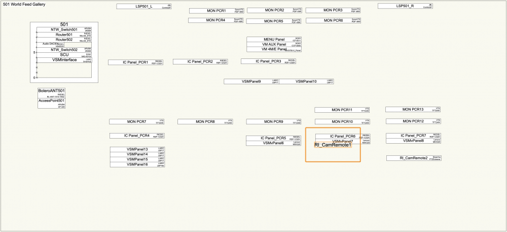
I try to print out a blockdiagram created with Connect CAD.
In my case I have a A0 plotter (Canon iPF770)
Scale of my Viewport is 1 : 1.625
Detail Level is set to "high"
Sheet Layer "Raster Rendering DPI" is set to 1200
I use the publish function to create a PDF file and then I print the pdf via the Mac OS Preview program.
In this font size the cable numbers get a bit blurry (maybe due to printer or settings?) and reading them always includes guessing.
Are there some settings that may affect the blurry effect on the print out or is it a combination of scaling too small and quality of the printer?
Or do i have to rearrange and split the actual block diagram into several viewports with a lower scale?
The objects on the Rack Elevation seem to have proportions for higher scaling.
-
4 hours ago, Conrad Preen said:
I was wondering if you would share with me a drawing using your SFP solution? I'd like to see it in action.
I'm not there, yet. Will pm you the file as soon as I'm a bit further. Or would you be happy with a small test file?
4 hours ago, Conrad Preen said:And by the way, I put in a request for you to become a Beta Tester so you should be hearing from Vectorworks at some point. If not let me know.
Someone from VW connected me and asked questions about our VW distributer, so I guess this is on it's way.
CHA
-
13 minutes ago, Conrad Preen said:
The equipment item in Vectorworks 2020 has a new checkbox Draw in Front View which is automatically set if the equipment is in a rack and is an option outside of rack. If this is checked the font size is adjustable with the menu -
Thank you @Conrad Preen. For my workflow I can work around the bug with the checkbox.
-
I'm not starting a new thread, because I think this definitely has the same topic "Font Size of Equipment Item (in Rack Elevation)", even though it feels like a different bug compared to the behaviour described above.
After updating rack elevation all drawn equipment appears in the rack elevation layer, but not all drawn equipment lives in racks.
On that layer I create layout rooms with racks and place the rack equipment in the racks. (as probably everybody)
The other equipment I put into the dedicated rooms more or less where they do appear in the real room.
With equipment in the racks I can edit the font (for me important is the font size) via the font drop down menu. The equipment not sitting in racks are not editable.
Even worse: if I move any of that equipment through the room the font and equipment size jumps unwanted to something completely new.
(The equipment in these rooms was put together in VW19 and then exported to VW20 looking fine.)
In the attached file you see what happens to a piece of equipment (high lighted) after moving it one pixel, ending up uneditable.
After putting the item into a rack, edit it in there, then I can move it in the room and it stays as edited.
-
The best solution for me at the moment is to add a connector type "SFP" in the user's connector list and then I created a virtual device with the according specs and connectors for every SFP I use. At the moment that's 20 different virtual devices for 20 different SFPs in use.
Doing it like this I have the SFP info on the Design Layer and a "clean" Rack Elevation.
Adequate naming and numbering (Device based) of the virtual SFP devices make them manageable in the reports.
I think about adding a custom field with IP addresses for SFPs converting SDI video directly into SMPTE2110-20 or SMPTE2022-6.
Don't know if this way fulfils everybody's needs, but I am quite happy with it.
-
 1
1
-
-
There's a wide variety of different SFPs around and most of the time you have no clue which one you will use when you create a device.
SFPs leading into SM or MM Fibre, leading into RX and TX or BiDi, leading into RJ45 or even SFP with SoC converting a CoAx video input (or output) directly into SMPTE2110 or other IP standards... this list probably is endless.(different bandwidth, different wavelength, QSFP...)
Do you have different SFPs as different connectors in you connector list and change the connector according to your setup. (This could cause problems when you have a Madi ring and RX and TX are coming from 2 different devices leading into one SFP connector.)
Of course you can create a unique device for every flavour of SFP and insert it into each connection, but this complicates the drawing quickly.
Is there a elegant and flexible way of handling directly the connector?
How are you doing this?
All best,
Christian
-
19 minutes ago, Conrad Preen said:
Should we simply drop the Make-Model in that case?
What do you think?
That's +1 for dropping.
Name is the 1st/main indicator.
Make&Model or details and can be viewed when the item is selected.
-
2
-
-
Hi Conrad,
Maybe I didn't explain too well, or you have read too quick...
I attached a picture of a full rack size item where the problem doesn't appear, but it's easier to see what I mean:
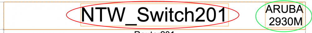
The Text drop down menu affects only the name (red circle), but I want to change the font size of Make and Model (green circle).
When you have a physical smaller device (e.g. half rack) these two labels overlap each other and I want to avoid this by using smaller text size.
Regards,
Christian
-
On 7/24/2020 at 7:18 AM, Conrad Preen said:
Regarding the "Renumber Device deletes the name" bug please me the file as a private message here on the forum. Also tell me the steps I need to take to reproduce. Thanks very much for reporting. We'll get that fixed right away.
Has that bug been fixed? I'm facing the same problem in VW2020 SP4.
-
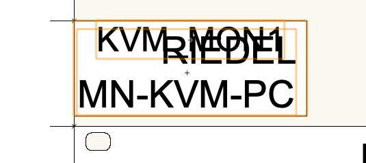
Whenever I have (physical) smaller devices in the Rack Elevation Layer the automated labelling of the Equipment Item's Name gets in the way of the Make and Model, as shown in the screenshot below.
The font attributes of the Name can easily be edited via the Text drop down in the top bar.
Where do I edit these attributes for the other label?
THX,
Chris
-
6 minutes ago, Conrad Preen said:
Hi Christian,
Can you send me PM a file that shows this misbehaviour? Sounds like a translation issue to me.
Hi Conrad,
will check in my backups to find a version with that behaviour. I replaced them already...
9 minutes ago, Conrad Preen said:Regarding genlock and network ports on frames, this is what we were discussing above. You create a device on your schematic with the same name as the rack frame and add the genlock and network sockets to it.
That sounds like a perfect solution to me!
Many thanks,
Christian
-
1
-
-
May I add a question regarding modular devices here, as well?
Is there a way to add sockets to a modular frame?
For example: I have modular frames with genlock and network connections.
At the moment adding another slot to the frame that carries a device with the needed connections seem to be the only workaround.
I realised that modular frames in VW20 (file converted from VW19) can't be edited anymore. Devices in slots stay there, but using "update rack elevation" puts them a second time on the rack elevation layer. Didn't find a workaround, but erasing and redrawing.
Similar behaviour of room elements: old rooms are still there, but can't be edited in size or name. New devices placed in "old" rooms don't pick up the location. Creating new rooms of the same name and size fixes this quickly. Is there a more elegant way of fixing this problem?
-
Hi Conrad,
Thanks for reply.
After finishing a connection VW needs a while until it is able to accept a new click (according to drawing size).
A key command can be hit in that period as many times as needed and the "connect next" function is executed after.
Maybe my computer is too slow for bigger drawings...
BR,
Chris
-
In the (old) stand alone version of ConnectCAD it was possible to create a key command for the "connect next" function. Now it seems that the only way to "connect next" is a doubly click on the next output. That really slows my workflow down. Especially when you have a router with 1024 I/Os and e.g. vision desks with 100+ inputs.
Was the key command option just forgotten while implementing ConnectCAD into VW and will it be available again soon?


How to change formatting of Arrow text
in ConnectCAD
Posted
Hi @Rob Sherman,
I think creating an own Sys-PortNames class (by copying and editing the standard) and applying this to the dedicated sockets will solve your described problem best.