


Phillip Tripp
-
Posts
41 -
Joined
-
Last visited
Content Type
Profiles
Forums
Events
Articles
Marionette
Store
Posts posted by Phillip Tripp
-
-
Does anyone have recommendations when out of memory warnings are triggered during a file purge? The Landmark file is 1.2GB, running on machine with 32GB RAM, 80GB free space on hard drive. The hard drive free space slowly gets used up until the out of memory message appears. Using Vectorworks 2023 SP5 on Windows.
-
Katarina,
You asked ….
WISH LIST
Some of these may be from lack of knowledge about specific tools and best practices for accomplishing tasks, but this is a first pass for site model and grading tool wish list items. We are currently on VW 2022 and some users in our office are still using VW 2019, depends on age of active projects. We paused upgrading to more recent versions due to item H below.
A. #1 wish list, a grade tool that allows the same grade tool functions along a curved line or continuous polyline, rather than limiting to a straight line.
B. #2 wish list, the ability to export the proposed contours as 3D polylines in DWG format for only the extents of the proposed contours within the grading limits area. Most consultants only want the new contours and not all contours for the entire proposed site model. The concept behind the grade limits line is the site model new contours should be tying into the existing contours at this moment, with slight tolerance for simplification settings potentially causing slight misalignment with original survey contours. If we send the entire proposed surface contours to a consultant, we have to send the grade limits line as well, and then they trim the proposed contour lines back to the grade limit object.
C. Editing existing grade tools. Would be great to edit all variables directly in OIP menu and not have to wait on a pop up menu specific to grade tools.
D. Editing existing grade tools. Some edits do not take effect the first time as in you want to change a slope or spot elevation in the grade tool window, click enter, no change. You have to repeat the process to make the desired change happen. Ideally, the changes would happen the first time.
E. Would be nice if after editing an existing grade tool setting, the screen highlighted briefly the adjacent connected grading tool modifiers that changed as a result of the edit, for the benefit of bringing attention the user of the consequence of their actions.
F. Would be nice if you could select a group of grading tools such as several along one continuous connected series and then edit the beginning elevation of the group and the final elevation of the group and have the slope be equal amongst all grading tool modifiers within that selected group. This eliminates having to edit each segment one at a time. I think currently editing more than one grade tool at the same time forces matching settings for both segments including elevations.
G. In 2019, we were able to have multiple grading modifier design layers and then pick and choose when design layer the site model would listen to which is fantastic for sharing grading options in a site model. In recent versions of VW, we ran into issues where if we duplicated one grading modifier design layer and then editing the duplicate, the original design layer modifier also changed. This meant we no longer were able to easily illustrate two distinctly different grading options with different grading modifiers on different layers. Ideally we can duplicate a design layer with option 1 grading modifiers, edit the duplicate grading modifiers called option 2, and the tell the site model to listen to option 1 or 2 as needed, without grading modifier changes in option 1 or 2 affecting each other when the site model settings are set to only listen to either option 1 or 2, but not both at the same time. I repeat this was an amazing benefit of VW2019.
H. I have already submitted this issue to VW in greater detail, but the short version of the issue in VW2022 which did not happen in VW2019, is the site model incorrectly reinterpreting contour lines rather than perfecting matching grading modifier contour lines. VW 2019 contour lines would create a site model with a contour lines that matched the desired grading modifier contour line. VW 2022 open line grading modifier only matches the bottom of hill contour lines and then invents it’s own final top of hill contour line rather than matching the final top of proposed hill open line grading modifier. Single isolated lines also exhibit the problem. Corrective measures include adding stakes and other modifiers to force the model to match the original desired open grading modifier line. Besides desired intent not behaving as anticipated, the bigger issue is receiving 100s of consultant 3D polylines and having our site model not accurately show the same contour lines because the site model is reinterpreting too much along the perimeter of grading areas, i.e. the final contour within a given area.
I. We noticed revit has issues imported vertical or near vertical wall cuts. The workaround has been to have two separate design layers, one that uses VW grading modifiers to visually show basement wall cut into the earth to make VW look good and then a separate grading modifier design layer that does not include the vertical wall cut and then let the revit architectural team use revit tools to recut the site model basement out again. We then switch the site model settings to listen to the right design layer before exporting files to the architects.
J. For cut fill earth work calculations, it would be ideal to be able to draw hardscapes for existing conditions and have the earthwork calculations evaluate changes in earth only between existing and proposed hardscape conditions. This means cut fill starting at the existing top of earth below vehicular pavement hardscape profile and comparing that to top of earth in the proposed new hardscape condition. I believe currently the cut fill calculations exclude the hardscape profile from the proposed condition but then compares that proposed earth elevation to the walking surface of all materials in the existing condition. I think this is true because it is not possible to assign hardscape to proposed or existing conditions. For the time being, we share disclaimers with contractors about the earthwork values for reasons above.
K. It would be good to be able to see both existing and proposed hardscape in sections to show changes before and after in one view. Maybe that is only possible with 2 overlapping viewports.
L. Would be nice if the site model section tool that shows finish grade lines for proposed and existing with spot elevation callouts could be directly integrated into the typical section tool with all options within the typical section OIP settings. Currently it is a separate process that requires copy pasting into section viewports, snapping to align. Also would be nice if spot elevation callouts could be auto aligned above or below the section with leader lines automatically lengthened to avoid spot elevations being autogenerated on top of each other and unreadable without hand moving each text object. This occurs when before and after section lines are very close to each other which happens in lots of conditions.
M. For the grading tool analysis features, it would be ideal if the analysis can identify slopes exceeding desired constraint settings to a finer level of calculation than currently possible. For instance, pavement codes require compliance with maximum slopes of 2% for accessibility but lets round down to 1.75% for construction tolerance. Then let’s consider different surfaces have different minimum slopes due to different surface textures to allow reasonable water flow and prevent sediment buildup or icy conditions, so minimum slope is 1% or sometimes 1.5% on irregular pavement. Now we are down to trying to flag shallow slopes below 1% or greater than 1.75%. I know there are physical limits based on the simplification settings and triangulation of the surface and probably a variety of other things, but if there are limits, perhaps including a warning within the analysis settings to avoid overpromising what can be accomplished by the analysis. If analysis at these small percentages is possible, perhaps allowing the user to draw a polygon around a specific area to limit the analysis and processing time to a small area of concern. I am sure it works fine for mass grading excessive slope analysis.
N. When running a grading tool modifier analysis and using the color to identify the issues, I think the color becomes permanent until overridden in another way. If a lot of grading tools are present, the analysis can take a long time and then the thought of doing it again just to get the color back to matching others is unpleasant. Especially if the analysis delivered undesirable results because the target goal of shallow slope analysis did not work very well.
O. Using grade stake tools to label a grading plan is not as flexible as desired in terms of positioning text labels once the tool displays the text. It seems to be fixed to specific settings.
P. It would be preferrable if grade stakes set to display the spot elevation of the proposed surface would update automatically if the proposed surface is edited. I believe currently they remain unchanged. Perhaps it can be a setting for the user to decide behavior. Currently we use grade tools to shape the surface and then manually create callouts for the specific spot elevations we think are useful for the contractor for construction, rather than show every grade tool spot elevation. I suppose some users would prefer the ability to decide individually which grade tool spot elevation is printable versus for model shaping only purposes. Our issue with that is we prefer to keep the text on grade tool modifiers small at 2pt to avoid the clutter of too much info in small spaces, which in turn is not suitable for printing.
Q. It would be nice if there was a setting for tracking any changes in these grade stake values that are set to automatically update if the site model changes, which would trigger a highlight and would stay highlighted until the user stopped tracking. This would allow the user to cloud the changes easily.
R. As an office, we have not used rood tools or curb line tools to know if they are already effective; but our initial attempts to use the tools proved challenging for us. If the tool does not already exist, it would be nice to have the ability to have a standalone curb tool that allows for any section profile and then allows the user to draw a polyline with grade tool representing the back of curb. The grades could change along the back of curb along that grade tool at nodes or the back of curb could be set to match adjacent pavement, or the gutter edge could match the other pavement. We also have instances where curb heights vary, not just as crosswalk curb cuts, but a typical 6 inch concrete curb might increase or decrease in height simply to address unique existing conditions. We can manually force the site model to illustrate all these conditions with multiple grade tools staked close to each other to draw unique vertical faces, but anything that can easier than that would be nice. I think hardscape material tools start to address some things by choosing datum elevation relative to the material component settings, but I don’t think it allows more than one datum for front and back faces of curbs.
S. On a side note about our general standard of practice in our office, we use the grade tool rather than path or road tools, as this allows us complete control of the surface. We do this to create realistic twinmotion graphics of courtyards and entire sites. Most projects do not include parking lots in the models or if they do, they are kept simple because we don’t have a quick technique to handling the curb appearance in custom situations, and in general, our focus is not the parking lot. We often have to adhere to accessibility code with a low tolerance of slopes between 1% and 1.75% and we find we are “warping” surfaces rather than proposing simple evenly sloped plains, as we tie into existing conditions. So high level of care in defining the surface and it is a lot of customization in different directions. The idea of a simple sloped plain in one direction is rarely a reality.
-
 2
2
-
-
- Popular Post
- Popular Post
Thank you for the effort in follow ups. I was able to visually demonstrate the change in behavior with VW staff this morning between 2022 and 2023. I used the exact same new contour lines in 2022 and 2023 (contours vs open edge lines), all based on the same existing contours, using a simple 100x100 feet model with simple shaped contour lines in an attempt to eliminate any odd unique conditions that might impact results. VW 2022 works great and as expected (model exactly matches desired contours) and VW 2023 mishandles the last contour in a series of contours or mishandles a single isolated contour. The reason I use the word "mishandles" is the model re-interprets the contour line we must exactly match because the contour line is coming from another consultant of the client. In a collaborative, multi-year project where we are receiving files from other consultants with changes every two weeks, with revised contours covering multiple acres, we cannot spend time adjusting contours afterwards because VW site model wants to reinterpret contour data received from others. To be clear, I am referring to straight line contours (open edge line) being ignored, not complex multi vertices lines where simplification has an impact. We have our own scope of work to focus on and cannot spend time re-drawing the work of others to maintain consistency of contractual drawings which is why it has a real impact on our office. I have passed along the example files to VW for further review. Thanks again for feedback.
-
5
-
Amending my concern, the issue appears to be related to the first or last desired contour in a series of proposed contour lines or the one contour in cases of a singular desired new contour. In these instances, the Open Edge Line modifier resorts to interpreting rather than implementing a contour at that designated location. We happened to be dealing with a vary flat area where singular contour edits were desired in several locations that triggered this feature quirk discussion.
-
3
-
-
That seems to not work the same as VW 2022 Contour Site Modifier. In VW 2022, Contour Site Modifier usually forced the site model to draw the contour where the contour site modifier was drawn. In VW 2023, the model interprets and we get mixed results (see Katarina's response below). We cannot have mixed results when we want to tell the site model to draw a contour in a specific location per a specific line. And we certainly can't explain to another professional office that we can't produce a model with contours matching their contours because VW dropped a feature. When I refer to contour, I mean a line with a whole number elevation assigned to it that should appear exactly in the spot designated, because the model illustrates whole number contours. Stating that to avoid any misunderstanding with Katarina's comment about site model settings determine what intervals contours appear at.
Katarina Ollikainen, VW employee, shared the following on the forums: “If you have precise contours you want to have in the site model, then by all means, use the open edge modifier, but remember that the site model settings will determine at what intervals you will see contours. If there are some contours you want to adjust at the end, then go into the 'Edit proposed Contours', but this is not an efficient workflow to start with.”
-
In VW 2022, we used (Create Objects from Shapes - Site Modifier - Contour) feature when we wanted to force a specific line to be a proposed contour in a site model. This was a helpful feature when working collaboratively with a civil engineer who might be responsible for stormwater management device new contours and our landscape architecture office would be responsible for new contours in other areas of the site. When we received the new contours from the civil, we would use this command to make their contours (contour site modifiers) and the model would update with contours almost exactly matching those contour lines in 99% of the cases. The effort involved was limited to assigning the correct elevation to the lines, but otherwise the process was straight forward. Also having their contours treated as site modifiers allowed us to continue using other site modifiers and not override their contours because their contours were also site modifiers.
In VW 2023, "Contour" is no longer an option in the (Create Objects from Shapes - Site Modifier) drop-down menu. How do we add new contour data from other consultants to our proposed site model and have our proposed site model illustrate their new contours exactly? Ideally with as little effort as was required in VW 2022.
-
Can anyone share how to re-enable the login prompt screen when starting Vectorworks, after someone has clicked the button to "don't show at startup"?
thanks in advance!
disregard - solved it - vectorworks preferences session tab "login settings".
-
1
-
-
Jeff, have you noticed with 2023 created hardscapes set to drape cut site model, the surface renders black when using the twinmotion visual effects clay render? Literally everything is white except pure black hardscapes. Change hardscapes to texture bed and hardscape material renders white in clay render mode. I am leaning towards new drape feature maybe doesn't play nice with all of twinmotion features or it is a VW setting on the material or hardscape that needs an adjustment and we haven't figured it out.
-
I was curious if there is a preferred method by all for illustrating vehicular/pedestrian curbs in 3D that is user friendly? Currently our office uses grade tools to custom grade everything, pretty much replacing hand/calculator grading with grade tools and then drape (2023) hardscape which works great. We could manually use grade tools to define top and bottom of curb and the surface would slope steeply within the profile of the curb, but I was curious if others are using a method that simplifies this effort. Obviously curbs vary in style on a project from raised 6 inches, transition to flush, rolled curbs, chamfered curbs, etc. We are not a parking lot focused office, so we haven't dived into parking or road tools yet, but the more 3D visuals include a portion of curb lines into the imagery, the more we need to figure this out.
-
1
-
-
I too have avoided the built in contour edit methods. I use the grade tool, pads, grade limits because you visually see a direct relationship between the objects representing your intentions and the results in the site model updates. If a civil engineer shares contour lines from their scope of work, we will add those to our file and convert to contours to assign a z elevation which also works fine. The trick to any of these is adding a grade limits line so the grading instructions are not carried out across the entire model in a strange way. Using these ways also lets you have multiple versions of grading concepts on different design layers in the same model and then you can pick can and choose which design layers the site model listens to.
-
2
-
-
I noticed that as well and have experienced that going back to 2019. Although, we've had other priorities and haven't pursued the GIS features heavily, so I don't know if it's an always present issue or just random files in our office.
-
😣 it's been too long since I've made that mistake. Thank you for pointing it out so quickly!!
-
1
-
-
I'm suspecting their might be a bad contour overlap and I just need to go over the contours closely looking for problems.
-
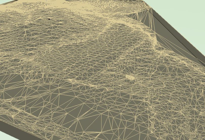
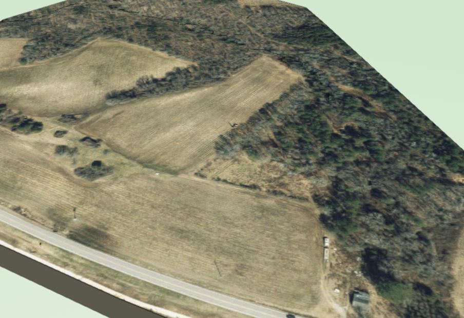
Are you able to switch to the typical 3D mesh colored elevation view option without the aerial? That's when I get the wireframe like appearance.
-
Does anyone know why the site model colored elevation mesh is rendering like this? The origin is georeferenced near the middle of the site. The aerial texture works fine in the site model settings, so it is geolocated correctly. File is attached. We are testing out VW 2023 and GIS tools.
-
And if you make friends with the BIM manager sending the revit DWGs, they should be able to save custom settings for future exports specific to your needs. For instance, if they have tagged all exterior walls, windows, and doors, they can have a custom export showing a really nice footprint only with no additional edits needed on the receiving end.
-
1
-
-
Our landscape architecture office typically converts DWG consultant files into VWX files and then references the converted VWX files into our Working File using the Layer Import method of referencing. This works well for most projects, but can become difficult to maintain in a timely manner on large complex projects with numerous consultants and frequent file exchanges. We recently started testing directly linking DWG files into our Working File using the Design Layer Viewport method of referencing and found it seems to work fine for our needs and has the potential to simplify our consultant file update process. Some projects have 8 architectural backgrounds or 20+ civil background files that update weekly, so setting up the ability to swap out DWG links without taking the time to convert them to VWX files would be beneficial. We'll still do color and lineweight overrides via the viewport properties of the reference which tends to be greying lines. We understand that the viewport visibility settings would be forced to be consistent across all sheet viewports, but that is what we typically do for all reference files except survey linework. We also noticed that if the original DWG author does not assign their objects to be color controlled by autocad layer, that Vectorworks cannot apply the color override which may be the one downside. The exception in our office to potentially using the Design Layer Viewport method of referencing, would be a survey reference file that we manually edit to move some existing linework onto demolition classes. Given a survey does not frequently update and we have to actually edit the file, unlike an architectural reference file, we will continue to convert a survey DWG into a VWX file. Our question is how to reference consultant DWG files that will remain as DWG files and also reference a survey VWX file into the same Working File. When we attempt to reference another VWX file into a VWX Working File using the Design Layer Viewport method of referencing, no objects from the VWX survey file are visible in the working file and no design layer viewport is created. It also appears we cannot have both a methods of file referencing in the same document, so we must choose one or the other. In the interest of reducing reference update processing time of consultant files, it seems we would choose the Design Layer Viewport method and then we would have to add the VWX survey linework directly to our Working File without referencing the survey, which is also fine; but we would like to hear from others if the Vectorworks referencing behavior described above is normal. We'd also be interested in hearing if others have encountered workflow issues using the Design Layer Viewport method of referencing for consultant DWG files.
Thank you for taking time to read.
-
I have been creating plans for 27 years across dozens of universities in NE and SE USA and have yet to encounter a forced standard for plant key abbreviations. With hundreds of plants on a project, we quickly run out of 2 letter keys within the same plant category and have to be creative, especially with multiple cultivars of the same species on the same project.
For Platanus occidentalis & Physocarpus opulifolius, we would do PLA OCC & PHY OPU, to help our staff more easily identify a plant during the middle of a presentation or construction visit without searching a lengthy schedule to decipher. The slightly longer abbreviation helps avoid the chances of duplicate plant keys. 6 letters vs 20+ letters in the plant tag still feels like a win. But like Jeff said, to each their own.
I too worry more about implying a standard that isn't practical for everyone. Plenty of those already.
-
2
-
-
I thought about the "many more levels" approach and "zero out" method and that is when I stopped out of common sense. Seems like an excessive level of effort for a work around and not sure I will like the end result. This was a one time curiosity experiment to see if there was any benefit. In the past, client's trust our judgement without any graphic proof other than plan overlay with boring locations. Would have been nice for the model to visually point out the obvious potential conflicts of footings and bad soils in a section format. I was not expecting the model to produce any soil layer volumes and always planned on producing reasonable bad soil volumes using traditional paper/pencil estimates.
I do appreciate the feedback!!
-
Curious if anyone has ever tried to use the "Add Geological Survey Points" tool for adding geotech boring test hole data for various soil types and depths. I created various textures and hatches and materials to represent the geotech report materials, added the components into the site model, and then after adding a single survey point, I realized the OIP options for the survey point appear to only let you edit the thicknesses of the components in the order the components are listed within the site model component window. In other words, it appears the entire site has to have a uniform layering of soil components where only the thickness of those components varies at each survey point, not the order of the component layers. In our region of piedmont North Carolina, below the Appalachian Mountains, the soil layer order varies at every survey point, 50 feet apart, pockets of fill dirt versus expansive clays, all useful to a contractor. I anticipated the site model having to make assumptions between geotech borings to address the mis-match of soil layer order from one geotech boring to another, but it seems that I cannot enter the data to match the geotech report in the first place. Am I missing a step? I watched the VW promo video for it and it too shows a perfect site of consistent soil types across the whole model. I googled images of Autodesk Civil 3D geotechnical module and that appears to accept varying soil component layer sequences at each survey point.
Thanks in advance for any input!
-
1
-
-
Curious if anyone has ever tried to use the "Add Geological Survey Points" tool for adding geotech boring test hole data for various soil types and depths. I created various textures and hatches and materials to represent the geotech report materials, added the components into the site model, and then after adding a single survey point, I realized the OIP options for the survey point appear to only let you edit the thicknesses of the components in the order the components are listed within the site model component window. In other words, it appears the entire site has to have a uniform layering of soil components where only the thickness of those components varies at each survey point, not the order of the component layers. In our region of piedmont North Carolina, below the Appalachian Mountains, the soil layer order varies at every survey point, 50 feet apart, pockets of fill dirt versus expansive clays, all useful to a contractor. I anticipated the site model having to make assumptions between geotech borings to address the mis-match of soil layer order from one geotech boring to another, but it seems that I cannot enter the data to match the geotech report in the first place. Am I missing a step? I watched the VW promo video for it and it too shows a perfect site of consistent soil types across the whole model. I googled images of Autodesk Civil 3D geotechnical module and that appears to accept varying soil component layer sequences at each survey point.
Thanks in advance for any input!
-
Just now, jeff prince said:
Death Ray is a proper architectural term to landscape architects 🙂
I do a lot of work in hot desert environments with reflected heat and radiation. Many plants which tolerate full sun in the desert will become crispy critters when located near glazing, facades, or swimming in a sea of pavement. Even projects in temperate climates can have plants die at the hands of the death ray shot from a shiny facade. A great example is Gehry's Walt Disney Concert Hall in LA, though no plant could survive that, it was melting cars.
Here's a good article that mentioned a few fryscapers:
https://gizmodo.com/a-brief-history-of-buildings-that-melt-things-1247657178
ahh yes, i know exactly what you mean and the concert hall story, but the term escaped my memory. thanks.
-
1
-
-
31 minutes ago, jeff prince said:
Thanks. I'll have to dig out the full mid-century modern treatment I came up with. It's similar to this one, but has more of an Eames inspired look with radial attributes signaling values in addition to these concentric arc examples.
Is solar death ray a joke for plants with parking lot sun baked survival skills?
-
8 minutes ago, jeff prince said:
I thought you might 🙂
Here's an early example a system I put together for one of my teams.
It works well for multi-cultural offices too, where English may be a second or third language.
In this example, the colors of the plant fill and bloom were from a symbolic palette that helped staff make sure they were pairing things according to our desired aesthetic. I would create a few key vignettes for different planting areas and then have my staff use that as a recipe for other areas. Think focal areas, nodes, foundation plantings, or special use situations such as adjacent to pools, parking islands, playgrounds, etc...
The best part of using a graphic language to code meaningful information is you can be sitting in front of a client reading a plan upside-down, and answer some basic information like when something blooms... without having to scramble. We all have moments where we forget things, especially if it's a plant you haven't used in a while and were focused on something else when the question was asked.

Really nice technique!
-
1
-

Purging Options With Out of Memory Pop Ups
in Troubleshooting
Posted
UPDATE:
We solved it by using a newer computer in the office with newer everything, 32GB RAM and 120GB free space. But still open to suggestions if others have tricks to pass along.