


Conrad Preen
-
Posts
1,031 -
Joined
-
Last visited
Content Type
Profiles
Forums
Events
Articles
Marionette
Store
Posts posted by Conrad Preen
-
-
Hi Matt
No worries! We could also do with getting an FAQ section here. I've started a thread called Did You Know where I post nuggets of info and how-to's. But I'd like to have the equivalent of support.connectcad.com. But yes, well worth checking out Vectorworks help. It's a pretty nice piece of software 😉
I'll get to your questions a bit later on.
Conrad
-
Hi DEZ
Check out this post https://forum.vectorworks.net/index.php?/topic/68748-signal-connection-type/&tab=comments#comment-339333
Explains how to add new signal and connector types.
Conrad
-
Hi Matt,
Not sure about the sage in my advice ( smells more like oregano to me 😉 ).
Any new makes/models, and any new variants you make of existing make/models are stored in the corresponding user folder database. I would not advise you to edit the device database file. First there is a good chance that you will corrupt it and have to re-install, secondly each time you upgrade Vectorworks your changes will be overwritten. User folder is much safer for your stuff.
So where is that elusive "user folder" I keep going on about. Let's check Vectorworks help. At the top-right of Vectorworks dialog boxes there is a little question mark. I went to the Vectorworks Preferences dialog and clicked that "?" and I found the text below.
Hope that helps
Conrad
From Vectorworks Help
Vectorworks preferences: User Folders tab
Click the User Folders tab to change the location of your user data folder, and to designate workgroup folders for sharing content with other users.
User data and preferences folder
The user data and preferences folder contains the Vectorworks files that are created and used by you. The user folder is automatically created outside of the Vectorworks installation folder so that your data and preferences remain undisturbed when the Vectorworks program is updated.
Within this folder, the program creates subfolders for Libraries, Plant Database (Vectorworks Landmark required), Plug-Ins, Renderworks, Settings, VWHelp, and Workspaces. The following customizations are automatically saved to the user folder.
● Vectorworks Preferences settings
● Workspace Editor changes
● Log files
● Resource Manager Favorite files
● SmartCursor settings
● Saved export and import options for DXF/DWG files
● Saved settings for the Eyedropper and Select Similar tools
● Settings for certain plug-ins, such as the Stair and Space tools
● Dialog box and palette positions
Additionally, you can manually add custom files to the Libraries folder in your user folder, to have resources such as symbols and hatches display in the Resource Manager and Resource Selector, or as default content in dialog boxes and palettes. See Creating custom resource libraries for more information.
Creating a new User Data and Preferences folder
The Vectorworks program automatically creates the following user data folder in the application data folder:
● Mac: /Users/<Username>/Library/Application Support/Vectorworks/2020
● Windows: C:\Users\<Username>\AppData\Roaming\Nemetschek\Vectorworks\2020
By default, both Mac and Windows hide the application data folder. If you use the default user folder, you might want to adjust your system settings to make hidden folders visible. Alternatively, create a new user folder in a more accessible location.
-
@JimWoodward Hey Jim, this sounds to me like Michael's wish could be a data visualization thing. What do you think?
Michael,
Your request is very specific to your way of doing drawings. Other people will have other ideas. I understand what you are trying to achieve. Making changes to the software for this purpose involves a whole process of implementation and extensive testing. So I think that we should first look for a solution in the existing powerful facilities of Vectorworks. Let's see if Jim has any thoughts on this.
Conrad
-
Hi Matt,
Thanks for the feedback. So here are some answers.
1. Cross-machine sync. We have harmonised with Vectorworks conventions on the use of the User folder path vs. Application folder. User folder mirrors the structure of the Application folder. You can add your own Signal and Connector type files in the user folder and your entries appear in the dropdowns. You can set up a Workgroup folder at a shared location and again files in this location add to the existing data.
2. Check out the connectCAD_Data/CableLengths.txt file, the default value is the first in the list.
3. This is exactly what Externals are used for - a terminating point for random cables.
4. Best way to handle this is to fake these with a virtual device i.e. a device with physical dimensions 0, 0 ,0.
5. This menu command is already in my plans but we didn't have the resources to do it this time around.
Best
Conrad
-
Hey Daniel
Surely with the right snap settings Option-click-drag would stay on the grid if the original object was correct? I always recommend turning off all snaps except snap-to-grid when doing schematics. And uncheck the Vectorworks preference Offset Duplications too. That way it's real hard to go off-grid.
Conrad
-
Hi Michael,
The skt_txt... symbol is the text displayed by the socket. The label text at the end of the arrow is built-in to the circuit object so it isn't really possible to change it. Since as you say this would be applied manually it might be better to look for another way to designate field cables. For example add a coloured dot next to the text.
This is a perfect application for Marionette. You could create a macro that can read the circuits source and destination location parameters and add extra graphics to the circuit. The trick to developing these things is to start off simple - just create a dot - then control the position of the dot and work backwards from there. Once you get it, it's not so intimidating.
Once you start getting the computer to work for you, you never look back.
Conrad
-
Hi Michael,
The color of circuits is set by default to the class color for the particular signal type. You can (or soon will be) able to change from using class color to your own color selection using the Vectorworks Attributes Palette i.e. in the normal way. The color is applied to the whole object including the arrow marker at the end. I don't see any way to change that short of you manually placing extra objects over each cable end. In any case ConnectCAD doesn't have a way of "knowing" what is a field cable, so you would have to assign this somehow. Am I missing anything?
I just tried overriding the marker style and found that I couldn't - I will look into why that is, maybe that would give you a visual indication.
Best
Conrad
-
Hi Josha
Nothing to worry about there. A virtual device is just one that has zero physical dimensions. Select the device and edit the dimensions in the Object Info Palette and when you use Update Rack Elevation to create equipment items from the devices it will work.
Conrad
-
 1
1
-
-
Yes, this is true.
Back in the 90's we used to use that system. I think it originated in Sony Broadcast and got adopted throughout the UK for a while. It has some basic limitations though. You very quickly run out of jackfield letters because you are using them up 2 at a time. The problem for us programmers is the "gymnastics" required throughout the application to support it. As we were upgrading the entire plug-in from Vectorscript to SDK we had to make some decisions. Of course since you ask I will give it some thought, but I can't promise anything.
Last time I looked, TSL had standardised on the A, B, C system with the ports numbered 1 - 50 on the top row and 51 - 99 on the bottom row regardless of jackfield size. This is quite neat because if a cable number ends in 50+ you know it's from the bottom row. If I were designing systems today I would use this method. It's so much more consistent.
Don't forget that ConnectCAD is a very open system and many customers use tools like Marionette and Python scripts to implement their own specific workflows. We at Vectorworks have to balance complexity and ease of use.
Best regards
Conrad
-
Hi Santtu
You are right and Vectorworks Align To Grid has an update in SP4 to handle this. The older Vectorscript command has been removed since in any case it was incompatible with the new Device objects.
Best
Conrad
-
Hi Matt
This one is quite easy to fix - in fact we already did so... what's happening is that the symbols Chuck made have no geometry in the center ( because they are circles ) and they have "fooled" our object detection functions. So, I just fixed that by editing the symbols like Niko did below for Scott. Just add line going thru the center and everything works again. The symbols in question are skt_con_IN, skt_con_IO and skt_con_OUT. Attached a file with the edited symbols.
Best regards
Conrad
On 3/23/2020 at 4:34 PM, Nikolay Zhelyazkov said:Hello @Scott Waller,
First, the disconnected devices, this is happening because you have circuits on the layer Room 8.10 Audio connected to devices on the layer Room 8.8 Audio. These circuits are not working in the VW2019 ConnectCAD too and that is why they are not working in VW2020.
About the disconnected circuits when creating new circuits. The problem here is that the symbols for sockets that you are using are tricking our detecting functions and we are not detecting the devices from the centers of the sockets. However, there is a workaround to that, if you simply add a line that intersects the socket symbol center and make it the same color as the background so that it is not visible, the connect tool will handle the sockets correctly. I am attaching a file with the fixed symbols that you can import and replace in your file and the Connect tool will start working again for these socket symbols.
Let me know if there is anything else.
Best Regards,
Nikolay Zhelyazkov
-
1
-
-
Hi Max
I have already logged an enhancement request for this. I would like to have this facility IF ... it is an action specifically triggered by the user and the extent and scope of the change to be applied is clear. That said, there are many reasons why ConnectCAD works the way it does.
- You can re-order the connectors for a specific device instance to un-cross connection lines - clearer drawings
- You can have only the relevant connectors actually used by the specific device instance - again clearer drawings
- You can have the same device in two places e.g. a master control switcher can be present on both the audio and video drawings - clarity again
- No unforeseen consequences - if editing a device edited every instance of that device then you would have to check each instance to be sure of your work
These are the reasons why 20 years ago I decided then to represent devices as groups and not symbols ( there are probably a few others too that I haven't remembered yet ). It wasn't the easy way for me - symbols would have been easier. But we would have lost the flexibility that has made ConnectCAD so popular.
I'm wondering if Select Similar might allow you to select the Devices you want to change? Then you could make the edit using the Object Info Palette or Attributes etc.
Best
Conrad
-
Hi Matt
Conrad here - now part of Vectorworks and still going strong!
First off, please send me the 2019 file in question so that I and my colleagues can investigate and resolve the issue. You can either post it here or mail it to me at cpreen@vectorworks.net.
Second happy to conference with you - these days I'm using Zoom rather than Skype. Send me an email and we'll set that up. I'll be happy to talk thru the latest with you. We have made quite a few changes to integrate better with Vectorworks but it's not as big a leap as it seems.
Best
Conrad
-
Hi Max,
The Prefix letter can be used in cable numbering formats e.g. S0123 - S for standard def serial digital. Use the %s tag to insert signal type prefix.
Conrad
-
1
-
-
Did you know...
that it's not so difficult to migrate your custom fields and their data from ConnectCAD 2018 to 2020? You can do it all using standard ConnectCAD and Vectorworks commands. Here's the how-to.
Migrating Custom parameters to ConnectCAD 2020 from ConnectCAD 2018.pdf
-
2
-
-
Did you know ...
that you can edit the Circuit > Cable Length parameter dropdown to have whatever values you want?
The default values are loaded for the file /Plug-Ins/connectCAD_Data/CableLengths.txt in the Vectorworks application folder. You can override this by putting a duplicate of the file in the corresponding user folder path and edit the file to your own needs.
-
Hi @twalker
You have a point regarding the connector defaults. I'll give it some thought and get back to you.
Custom panels are handled by the Connector Panel Tool. This tool is created to model the situation you describe where you have a bunch of chassis connector mounted on a sheet metal plate. On schematics you use the tool to place the devices that represent your panel connectors and where they go in terms of connectivity. There are two types of Connector Panel device:
- Input (green) - where the cable of the left has a connector and the cable on the right terminates directly on the chassis connector (type <--)
- Output (red) - where the cable of the right has a connector and the cable on the left terminates directly on the chassis connector (type -->)
And on a layout layer you can model these as Equipment Items. And of course they can be set to standard rack dimensions. There is a how-to article in
that talks in more detail about this.
Best regards
Conrad
-
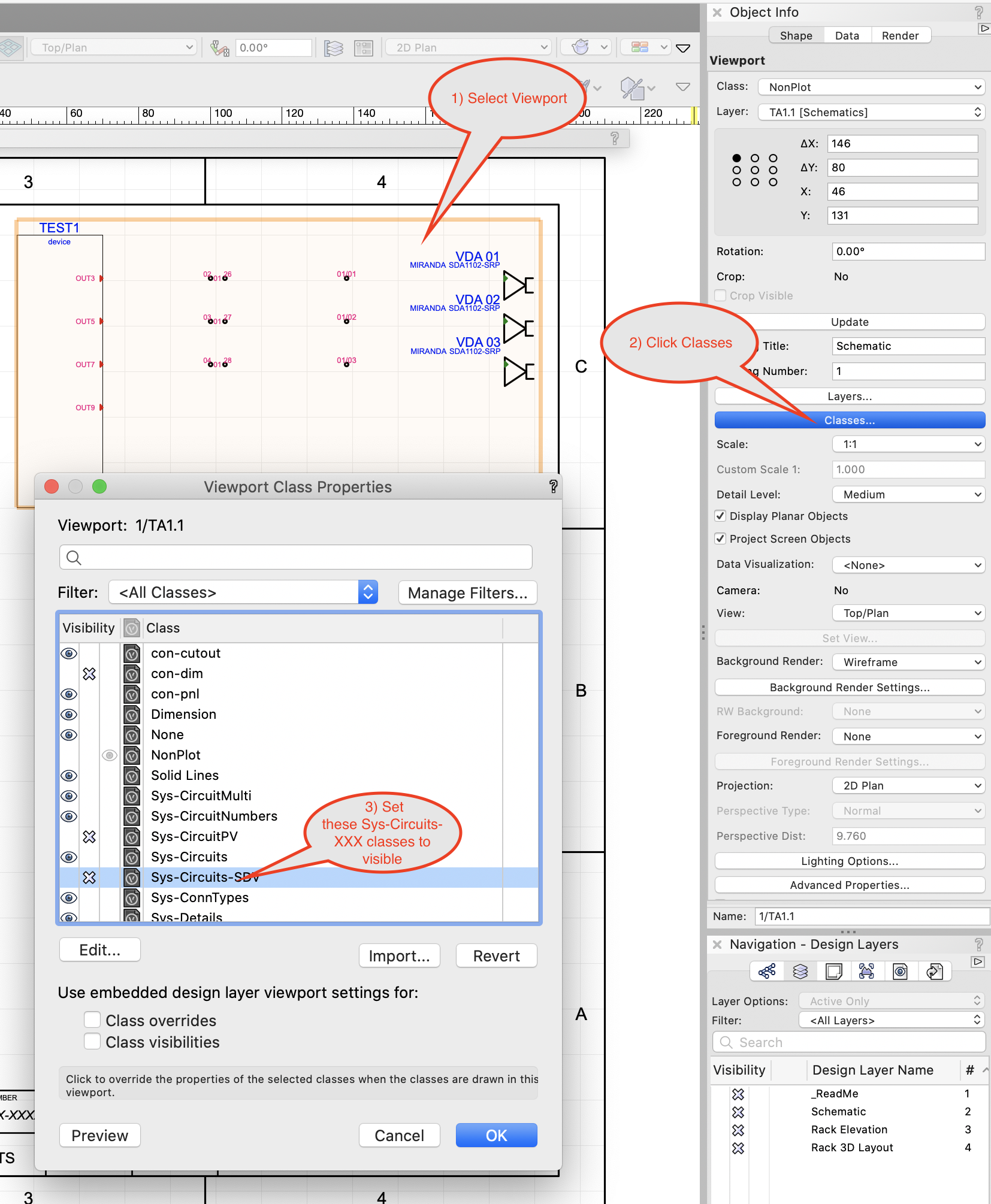
Hi Scott,
Sounds like the Sys-Circuits-xxx classes are set to invisible in the Viewport on the Sheet Layer. You can have different Class visibilities in Viewports compared to Design Layers. You can even override Class Attributes to change the colors of stuff in Viewports without affecting the Design Layer. Another example of the awesome power of Vectorworks I'm afraid 😉 . I did you a quick step-by-step how-to screenshot.
If this doesn't fix it be sure to let me know.
Conrad

-
1
-
-
Hello!
Jackfields and term panels don't have a signal type. We have a special signal type --- which denotes a passive device. Circuits are designed to ignore passive devices when they calculate the their signal type.
Regarding connector types, which jackfields and term panels are not right for you?
Best regards
Conrad
-
Hi James
At the moment the number of blocks is not adjustable, but I will make sure we take care of that ASAP. and let you know. Thanks for reaching out. Thank you also for showing me the detail workflow you need for these DIN blocks. This has been added to my plans and I will create a solution for this.
Conrad
-
Hello James
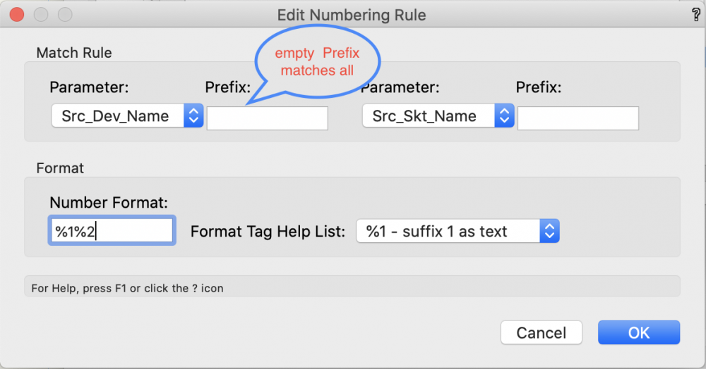
I've been looking into the numbering issue that you showed me. In fact it all works as designed but that doesn't mean it's easy to use. Even I had difficulty figuring it out. So, I have put a ToDo item for myself to review the way we define numbering rules and figure out a way to make them easier to understand.
To come back to your requirement. To extra the Source Device Name into the Suffix you should leave the match field empty. That way the entire text ends up in the suffix. Then to insert that suffix in the cable number use %1, or %2 for the second suffix. These are in the format help dropdown. Here's a picture of what I mean.
This rule creates a cable number <source device name><source socket name>.
The rest works as designed though I do see that I can't add a constant number to the #1 and #2 tags. I'll fix that, but it really isn't a showstopper.
Finally, I'd also recommend looking the Spotlight Numbering command. This has a lot of powerful options and cane be used with ConnectCAD objects. The approach is very different and complementary to what we do. So you may find stuff in there that helps you out also.
Regarding the duplicated objects, I'm still looking into that. I'll post replies here so others can also benefit.
Conrad
-
Hey Scott
My bet is that you did the one drawing and then duplicated the layer and used that to make the other drawing. Did I guess right? Unfortunately that doesn't work in ConnectCAD 2018 because nothing tells the duplicate Circuit that it's a new thing and it needs to detect what it's connected to. So like a good (but dumb) computer thing it stayed connected to the devices on the old layer.
The good news is that now as part of Vectorworks we have access to way better methods of dealing with all this. So, from now on it's nothing but blue skies 🙂
Best regards
Conrad
-
Hello James,
That sounds a bit weird. Can you show me? Skype 'connectcad'. I'm online now.
Conrad

Adding Makes / Manufactures in Device Builder
in ConnectCAD
Posted
Hi Charlie
Just checking that here on my Mac. What I'm seeing is that if I've already selected an existing Make, I don't get the option of New... in the Model dropdown. If I create a new Make I also can create a new Model. Is that what you are seeing?
BTW editing ConnectCAD Devices DB.txt isn't a good idea, not impossible, there's just a lot to go wrong when we humans do it.
Conrad