


Conrad Preen
-
Posts
1,031 -
Joined
-
Last visited
Content Type
Profiles
Forums
Events
Articles
Marionette
Store
Posts posted by Conrad Preen
-
-
OK. You can however rest assured that any material sent to Vectorworks is always treated as highly confidential and would never be share without your consent.
-
Would it be possible for you to send me the file in a PM so we can see what's going on? Inconsistency is a bug so we need to fix that.
Conrad
-
Hi Ryan
The idea here is to save space where the connections are very short and the path is not complex. If you separate your devices more and leave some room both numbers will be drawn.
Conrad
-
Please check
Conrad
-
The 3D rack object has one purpose - to allow you to visualise 2D racks and their contents on floor plans.
You construct your rack layout by placing 2D Racks and dragging your equipment items into them. When the equipment item is in a rack it draws itself in front view, when it's outside the rack it draws itself in current layer view. This is a change from previous versions of ConnectCAD and was made to avoid the need for a special layer name Rack Elevation. This is better for people who work in other languages than English.
Conrad
-
Thank you Ean,
Listen everyone! Near the top of this thread I have posted a step-by-step guide to how custom parameters are handled in 2020. It explains exactly how to add parameters and how to visualise them. It does not tell you how to add a static text label - if you're confident enough to start customising anything I think it's safe to assume you know how to add a simple text object! A bit further down this thread you'll find how to add custom fields in reports. Again it shows a clear example of what to do.
I would be the first to agree that it is hard to find information in this forum. This is obvious from the fact that I have to answer the same questions over and over. Fixing that has made it to the top of my to-do list.
Meanwhile please check the thread "Did you know" for how-to's it can save you a frustrating wait for a reply here.
Thanks!!!
Conrad
-
If you edit the Custom Params in the app folder please back up the file somewhere safe because it will be overwritten on upgrade. The user folder essentially mirrors the app folder paths. Plug-ins/connectCAD_Data is the place where you can put files to add custom signal and connector types, and your own version of CustomParams.txt etc.
It's different because we improved it. Much easier moving forward to carry these extra fields with you.
Conrad
-
Actually Ean, it doesn't seem sensible to clutter up the Device Builder when it really is this simple. Check out the Did you know thread for a guide on visualizing user fields.
Best
Conrad

-
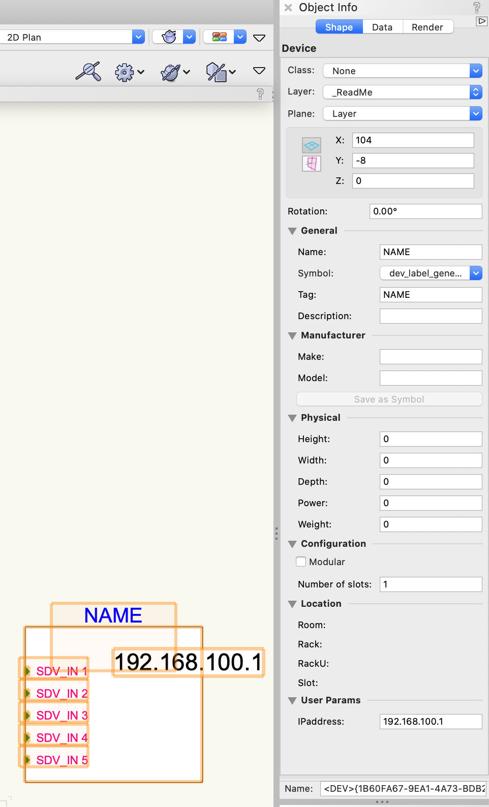
No need to flounder 🙂 for sure it is in the Object Info Pallete available immediately you create the device.
-
 1
1
-
-
Hi Ean,
You're right on both counts I think. IP is close to a standard requirement these days and yes, I think user fields should be added to the Device Builder dialog. I reckon with IP address the best way would be to ship with this enabled as a way to introduce custom fields. Interested to hear opinions.
Conrad
NB strike the idea of adding custom fields to the Device Builder. We don't need that - you can see them in the OIP as soon as the device is created.
-
I hate to say this but... do these names have to be so long?
-
No, that isn't set up. Could you send me a quick screen shot of the problem?
-
Hi Danny,
Select the equipment items whose text size you want to change, go to the Text > Size menu and reduce the size.
Conrad
-
Thanks Matt!
You can also go a long way using the Create report command in Vectorworks but I would agree that Excel gives you much more analysis. Back in the day I was a great fan of Pivot Tables in Excel. Check them out!
Conrad
-
Hi Mike
Can you send me the file that doesn't convert as a PM and let me know what steps exactly I need to follow to break it? Also I note you are using those circular sockets so please check out this thread too. https://forum.vectorworks.net/index.php?/topic/70504-older-connectcad-files-broken-in-2020/
Conrad
-
Hi @mcschaefer
Yes you are right - that's how it works.
Not sure about messing with the application ConnectCAD Devices DB.txt file. We can only support the standard release versions of Vectorworks.
Conrad
-
Hi Frans
Thanks for your forthright comments. Right now it works the way I told you. The Update Rack Elevation command does most of the work for you - all you have to do is drag and drop your equipment into racks and rooms. Most people find that quite efficient. Obviously I'll keep your workflow in mind but any change would be for a future version.
Thanks!
Conrad
-
Hi Mike,
The user signal and connector types files are located in
Mac: /Users/<Username>/Library/Application\ Support/Vectorworks/2020/Plug-ins/connectCAD_Data
Windows: C:\Users\<Username>\AppData\Roaming\Nemetschek\Vectorworks\2020\Plug-ins\connectCAD_Data
In 2020 as part of Vectorworks now, we have changed things to match the Vectorworks way of doing things. Create corresponding SignalTypes.txt and ConnectorTypes.txt files in the User path and add your own signals and connectors here. These are appended to the data in the application folder. This is much better than editing the app folder because that gets replaced during a service pack upgrade.
Conrad
-
Rooms live on the layout layer.
You need to do Update Rack Elevation to put whatever devices are on the current layer onto the layer Rack Elevation as Equipment Item objects. Then draw your Room there and maybe place a Rack too. Then you can assign Equipment Items to Rooms and Racks just by drag - dropping them in.
When you go back to your schematic you'll see that the location data is entered in the devices and displayed just under the description text.
Conrad
-
Hi Frans Jan,
Essentially our DIN rail tool is an extension of jackfields and term panels (which are all the same under the hood). and came out of a customer request. For panels generally, we had the option of using an alpabetic labelling namespace A,B,C... and the problem with this was that in big installations you ran out of panel names. So, I added the notion of panel group to extend the namespace.
Then along came this customer who had a very specific way of labeling DIN rail terminal blocks requiring an X before the rest of the name. So the group ID for DIN rail terminals became X. Don't like it? Select the DIN rail tool, find the little spanner icon top-left (tool prefs), change it to whatever you want.
1 hour ago, fjtb said:overall we are working on cable level in Connectcad, and in the DIN rail terminal tool, we are on single wire level (I assume). How to manage this difference.
When you start to go below the cable level what you do is very much dependent on your application. ConnectCAD doesn't force any particular conventions upon you. I would try to factor out the standard interconnections and use our tools to handle these since they are usually the bulk of the wiring, and then do special breakout drawings for the exceptions.
I have been in conversation with another customer about extending the DIN rail system to make it mode visual. I'd certainly be interested in your thoughts too. Maybe a sample drawing of what would work for you?
Best
Conrad
-
Hi fjtb,
Yes that's true the setting is gone. The Device Builder in 2020 calculates the width based on the the text lengths of the device and socket display tags. It is engineered to ensure that whatever device is created looks good. This change was made to assist users who rightly complained of the inconvenience incurred when they had entered all the device data only to discover that the device was not wide enough for the text they entered. Rather than add to the miasma of settings we opted to make it just work.
As far as I understand you can still use your device symbols that you created in the previous version. I'm not exactly certain what the problem is that needs fixing?
Conrad
-
1
-
-
Hi Max,
I don't see why not. Give it a shot and if you have any specific questions I'll be happy to help.
Conrad
-
Hi Charlie
You are not missing anything! In fact we just fixed a minor issue as a result of your input - many thanks!
Love ConnectCAD now? Wait 'til you see the next version !!! 😉
Conrad
-
1
-
-
Hi Daniel
As I said to Max, I have already logged an enhancement request.
Of course there are sound workflow reasons for being able to make mass edits. This is the right way to go for the reasons I discussed above. if we had "Devices as symbols" it would then be much harder then to engineer exceptions. A Mass Edit command is a do-able thing and we will make that happen.
Meanwhile I want to try and turn you guys on to the possibilities of automating your more specialised workflows. Computers are by nature programmable, and there is no reason for anyone to have to perform repetitive tasks any more. I'd really recommend getting into Marionette. It's is an easy way to begin putting your feet up while the computer takes care of the work.
Conrad
Did you know...
in ConnectCAD
Posted
Custom fields in 2020 explained
And how to use them in worksheets reports.
CustomFields1.pdf CustomFields2.pdf