Wimads
-
Posts
11 -
Joined
-
Last visited
-
No revision data in title block for Fundamentals?
Wimads replied to Wimads's question in Troubleshooting
Is there a complete feature/command list somewhere that lists what functionality is available for different versions of Vecotorworks? I run into wishing for functionality every now and then that I cannot seem to find, and would like to be able to verify if that is due to my version of Vecotorworks, or me looking in the wrong place. As a second question: If I upgrade my version of vectorworks, and create a template with a title block that uses the revision data functionality as I intended in my OP. Will someone with a Fundamentals license be able to use that template including the Revision data functionality of the titleblock? Or will that functionality be crippled for that person? -
No revision data in title block for Fundamentals?
Wimads replied to Wimads's question in Troubleshooting
Alright, understood. That's a pity... -
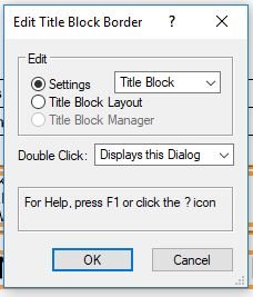
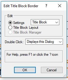
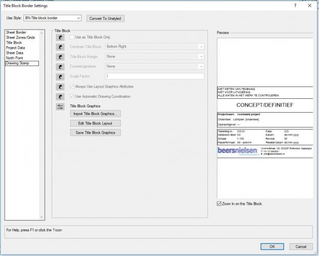
Hi all, I am working on getting my company's vectorworks template to a bit more professional standard. Hence I am working on a more automated title block. (before it was only a manually drawn title block) I am getting it to work fine so fare using the title block border command. However, I now wanted to also include a revision history, and that is where I am getting confused. Everything I find online on that points to the title block manager, which is a greyed out option for me. And to a revision data tab in the title block settings, which is missing for me. (see screen shots). Am I doing something wrong, or is it simply functionality that is not included in Fundamentals?
-
Thanks for the suggestions. Tried all, and eventhough it makes a bit of a difference it is still slowing down my model too much. I'll go with the render texture option I guess, if I really want to show the perforation.
-
Alright, thank you markdd. I guess I'll just leave the perforations out then. It is not critical to have it in the model, would just have been nice. Some positions of other parts depend on it, but that can be determined without 3D geometry as well.
-
Hi all, I am trying to create a simple perforated metal sheet in vectorworks. 250x350x1mm sheet, 4mm diameter perforations 6mm apart. I basically create an array of cylinders in the pattern I want, and then subtract those from a 250x350x1mm solid. But that means subtracting a few hundred solids, so it takes a while to perform the action(though it does work without crashing) and the subtracted solid then is slowing down my model considerably. I could of course omit the perforations, but I would prefer not to in this case, because other parts of the model depend on it. Is there any way to do this that requires less resources?
-
Keeping text pt size constant when changing layer scale
Wimads replied to Wimads's question in Troubleshooting
Alright, thanks for the explanations. I will try out a bit tomorrow. We are a small company, with not a very large amount of experience in 2Dcad drawing. Most people are self thought in vectorworks, including me, so a lot of different workflows have formed between employees. And since the office has been growing in number, a need for some standardization is now emerging, so working in someone else's document isn't as much of a pain as it is right now. Seeing your workflows makes me think some more education in vectorworks might also be useful, before attempting too elaborate a standard protocol for our workflow. -
Keeping text pt size constant when changing layer scale
Wimads replied to Wimads's question in Troubleshooting
By "in annotation", do you mean on sheet layer? Sorry, not native English, so might have misunderstood. But if that is what you mean, I am not sure how that is a workable solution for anythiong except actual annotation? If any scale changes, you'd need to reposition all text that is dependent on location in drawing. Anyway, keeping layer scale and viewport scale aligned, and not missing that scale text checkbox should be a workable solution for most of the stuff we do, except text in symbols. To give some context, I work for a lightning design agency, so basically our most common drawing work consists of specifying position and specification of fixtures. Meaning symbols for each fixture, that have a label like "B2" in them. If the font size of that "B2" could in some way remain constant on the sheet layer, that would be perfect. -
Keeping text pt size constant when changing layer scale
Wimads replied to Wimads's question in Troubleshooting
Of course it is as simple as that! How did I miss that checkbox.. Thanks a lot! EDIT: Or well, that was almost the complete answer... but as it turns out, that only works for normal text, but not for text inside symbols... But I guess for most projects that won't be a huge issue. By the time there are so many symbols it becomes a tedious task to adjust all of them, I would hope the right scale will have been determined already. -
Keeping text pt size constant when changing layer scale
Wimads replied to Wimads's question in Troubleshooting
@markdd That is more of a workaround than a real solution. The problem is that all existing text is scaled to for example 6pt when the in the design layer scale is adjusted. Any new text created after scaling will still have the 12pt font size I want to specify as a standard for our company. Of course I could simply start using 6pt as the standard font size in that particular document to work around the problem, and then adjust by scaling the text in the viewport. But it is not really a good solution, considering not everyone in the company is equally handy with computers. Some people will simply leave the workaround and settle with the too small font for example. Additionally there will be frequently people working on documents that were created by other colleagues - so it is good to have a standard that works the same for every document, and not with a workaround for some of the documents that happen to be a different scale than 1:100. -
Hi all, I am working on standardizing a template for the company I work at, for all our 2D drawings. I am running into an issue regarding layer scales and text size. Most drawings we make are good with a 1:100 scale. Hence I set the standard design layer to a 1:100 scale, and use a 1:100 scale for viewports. I want my text size to always appear 12pt when printed - and as long as layer scale and viewport scale are identical, this works great. The problem occurs when changing the scale on an already existing drawing. Sometimes, while setting up a drawing, at a later point you find out for example 1:200 is more suitable. My logic then tells me to scale both the layer and viewport to 1:200, to keep both scales identical so 12pt text remains 12pt text. However, the problem with an existing drawing is that any existing text in the design layer is also scaled from 12pt to 6pt in this scenario. I would like to prevent this from happening, meaning my text should be 12pt no matter any change in the layer scale. Is there any way to accomplish this?