


Daniel Dickman
-
Posts
101 -
Joined
-
Last visited
Content Type
Profiles
Forums
Events
Articles
Marionette
Store
Posts posted by Daniel Dickman
-
-
Is there any easy way to find and select all the devices of the same make and model? I'm thinking similar to the Spotlight find and modify tool, but I can't seem to use that tool for ConnectCAD devices.
Using VW2022.
-
21 hours ago, Ross McLee said:
but thank goodness for snap to grid tool to bring it back in line (ctrl+ - )
How did I not know about this short cut!!!! Life changing!
-
I had this same issue the other day with Vectorworks on PC. I reinstalled the v2.6 plugin from the MA website and the issue was resolved.
-
I've run into a similar issue where I needed unique names and still wanted to repeat numbering in certain locations. My fix has been to add a location identifier into the device name. So your device names could look something like...
'"Room1 - AVoIP 1"
"Room1 - AVoIP 2"
"Room1 - AVoIP 3"
"Room2 - AVoIP 1"
"Room2 - AVoIP 2"
"Room2 - AVoIP 3"
-
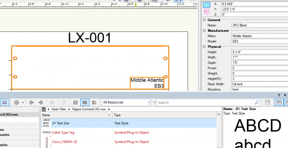
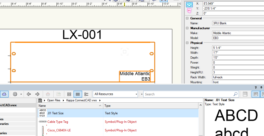
@joneztria I'm not sure how Jim was doing this, but I was able to accomplish this by creating a Text Style in the resource manager. Set the text size to .01 and then drag the text style from the resource manger on to the equipment item in your rack elevation.
-
Sounds great Conrad! The only thing I would mention, is that we should still have the ability to place these cabinets inside of rooms.
-
6 minutes ago, Nikolay Zhelyazkov said:
- Actually, you are asking about 2D equipment in 2D rack or about 3D racks? Because tagging of 2D equipment is absolutely possible.
Yes just talking about 2D racks. Looking to have tags, just like we do on the schematic layer.
-
Is there anyway to add a tag to an Equipment Item in a rack elevation? I'm finding some of my device names are long and would like to use a tag for a more concise text on the elevation.
-
Hey Conrad,
Another connector arrow questions for ya.
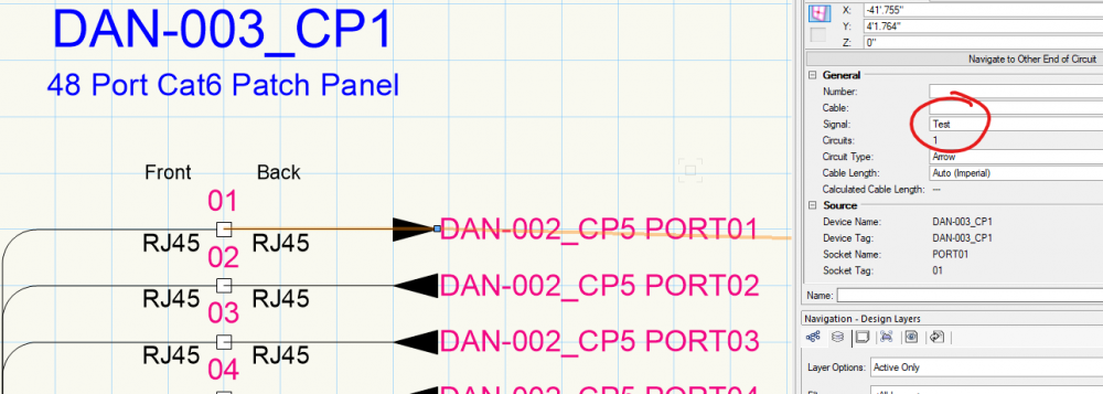
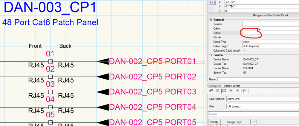
I've noticed that If I add a signal type to an arrow circuit, that the direction of the arrow flips. See below.. Why does adding a signal type change the arrow?
-
1 hour ago, Conrad Preen said:
So, these enclosures are a bit like a rack with a different look, and without RU heights
Yes that's it! Excited to see where you head with this!
-
In the instance of devices inside an enclosure, I think I'm less concerned with where it is inside. Just that fact that it IS inside. But it is an interesting thought regarding designing an enclosure layout. It would be cool to design their layout similar to how we do CTP panels with a front view.
As far as the Location hierarchy goes, Buildings would be at the top level... Inside Buildings are Rooms.....and Inside rooms are Racks or Enclosures.
-
Just sent you an email.
-
Hey friends,
I'm working on a show where we have a number of devices in Hoffman style enclosures. Is there way where instead of placing gear inside a rack, I could define another location? (In this case an enclosure.
Also along these lines, in addition to room/rack/enclosure I'd like to define a building where specific rooms are located. How would I go about this?
I imagine I could just use custom parameters to define some of these locations, but it would be cool to have other versions layout room tool for buildings or enclosures.
Thoughts?
-
Speaking of Arrow Connections....
I've been working on drawing up lots and lots of fiber cable and associated OTPs.
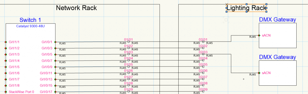
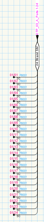
I'm curious, is there a way for me to use 1 arrow connection for multiple circuit lines? For example lets say I have a 24 strand fiber cable, in ConnectCAD I would like to show each strand landing at it's respective port on an OTP but for clarity I am bussing the circuits together to better indicate that this is indeed just 1 cable.
Here is an example of what I'm thinking (this is mocked up). My thinking is that I would like the ability to have 1 arrow connection for all strands in that cable, and the arrow text would indicate what OTP it is landing at and the associated ports.

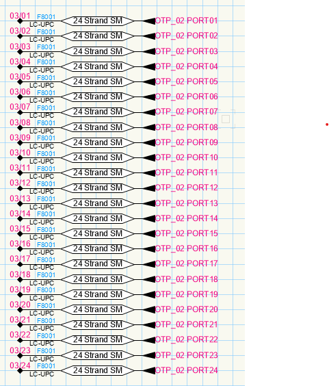
Currently using arrow connections looks like this. At first glance this could be mistaken for 24 different cables.
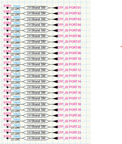
Any tips for using arrow connections on multi-circuit cables?
-
Here is the combined Spotlight-ConnectCAD workspace if anyone would like to use it.
-
 1
1
-
-
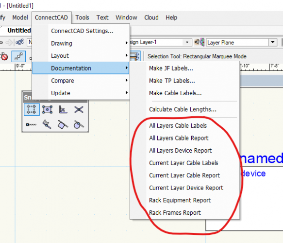
That did the trick!
So what exactly is happening there that allows 1 menu item in the workspace editor to then appear as 8 different menu items in the actual menu?
Thanks Conrad!
-
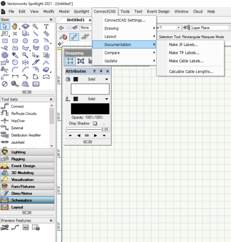
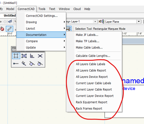
I'm working on building a custom workspace that combines Spotlight and ConnectCAD. I've recreated all toolsets and menu items but I can't figure out how to add the various report commands to the documentation menu. I imagine these are either scripts or plugins.. does anyone know how to add these to a menu in the workspace editor?
-
Is it possible to create a report that shows which devices are connected to a particular device? The specific example I am thinking of is for network switches. I would like to create a report that tells me which device is plugged into which port on the network switch. The challenge here is that VW/ConnectCAD will need to ignore the passive devices such as Data Term Panels that are between the switch and the end devices.
Any thoughts on how to accomplish this?
-
Great, thanks Nikolay
-
Hey friends,
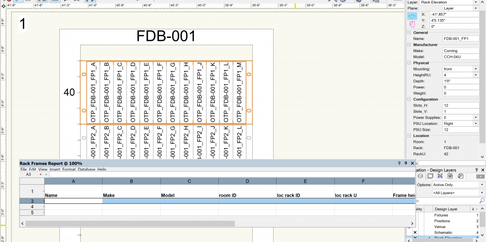
I'm experimenting with the rack frame tool in ConnectCAD 2021. I've added a couple frames and populated them with gear. When I attempt to create a rack frame report, the worksheet is always empty. What am I missing here?
-
Hey VW team,
Where can we find a comprehensive list of new features and improvements for ConnectCAD 2021?
-
17 hours ago, mschoeffmann said:
Yes. So then the panel is a single device which can be labeled and displayed like every other device? This sounds perfect.
Thanks
+1. Would love to see this
-
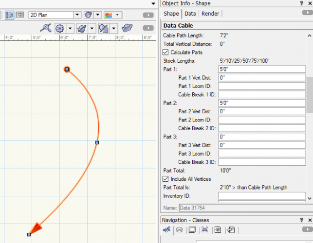
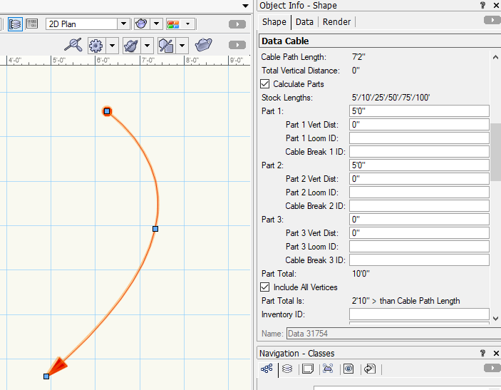
In the image below, I have a data cable created from the "Make Data Chain" function. As you can see the cable is 7'2" long but VW is breaking it into two 5' cables instead of one 10'.
Is this expected behavior?
-
Thanks @markdd!
I finally have this working. The part that I was not understanding was that I needed to convert to hanging position in plan view with the ladder flat on the ground prior to rotating into place. I now realize that, that this particular detail was what started this entire thread from the beginning. But for some reason even after reading all of these posts for the last couple months, I just could not comprehend drawing 3D geometry in this way.
Thank you everyone for all of your help in this thread.
-
1
-


Find and select devices of same make/model
in ConnectCAD
Posted
Thanks Pat!