Jainsworth
-
Posts
24 -
Joined
-
Last visited
Content Type
Profiles
Forums
Events
Articles
Marionette
Store
Everything posted by Jainsworth
-
@Benson Shaw Thank you for these tips! You have pretty much answered my question so now to go away and test, I especially like the hatching on the inside option 😁 Thanks Joe
-
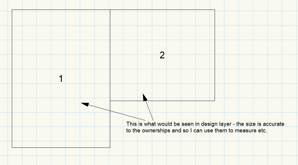
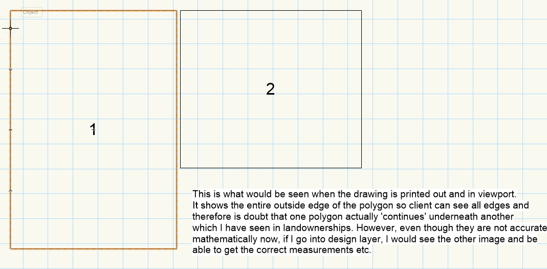
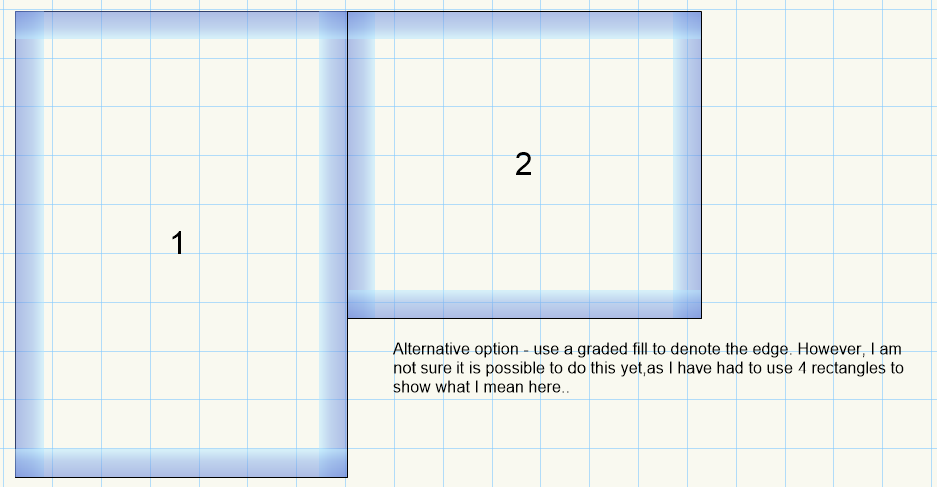
@Benson Shaw , Your tips are all helpful and thanks very much for the file! I can see what you are doing and especially the remove edge tool I haven't used before. I've attached an images of what I am basically after. To add some context. I often work with various landownerships, and some sites have 30+ ownerships of different types, and wildly different shapes, which I represent on drawings using outline polygons which go around the edge of the ownership. Sometimes, these ownerships sit right alongside the other ones, but sometimes they overlap. You can see by the images that I basically want to 'display' something different to what is actually drawn to help clients etc understand what is going on at the site a little easier. A possible option I have just thought of with the outlines - I am not sure, but it might be possible to use the gradient fill option to show the edges (seen in image attached 'graded fill option'). Hope this makes it a little clearer! Thanks again for your tips, and hopefully I am not talking rubbish! Joe

-
@halfcouple Fair enough then. I have had a bit of a play with that tool, so maybe I should investigate further. Thanks for the tips anyway. I am still figuring out the fill gradient mechanisms so maybe that is an alternative! Thanks Joe
-
@halfcouple I haven't tried that no, although it would make the sheet layer a lot more complicated. I assume that it is not possible to do what I am asking then! A shame, as it means I can show two borders next to each other whilst keeping their correct mesaurements. Unless there is a way of making a gradient fill that fades away from the outline?
-
@Benson Shaw Hi Benson Shaw, yes I am aware of that as a workaround. I take it that you cannot do that exact configuration of shapes you have used there, and make them both solid, only to have the viewport display them adjacent to each other but in the actual drawing still be like that? Thanks Joe
-
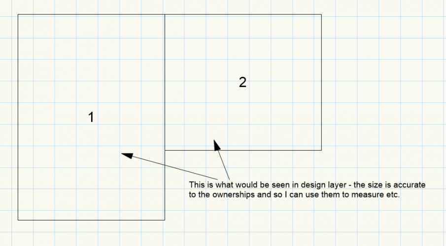
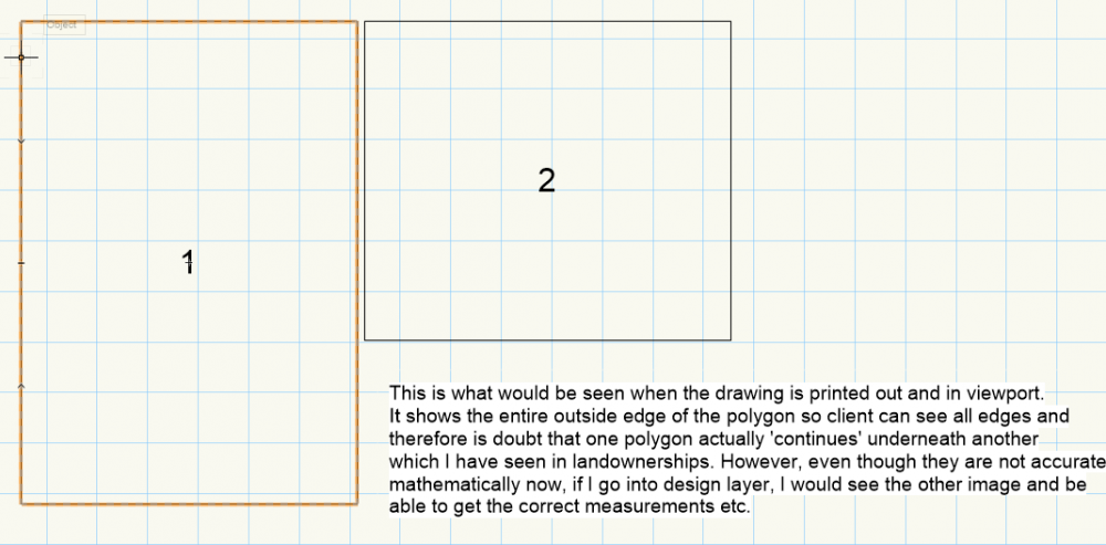
Hi all, I want to display two polygons, which share a boundary, in my sheet layer. Although the boundary that they share is the same X and Y coordinates along the shared boundary, I would like for the sheet layer to show them directly next to each other when it comes to sheet layer and printing. This way, the m2 of the shapes are accurate, but the display allows you to see the 2 polygons next to each other completely. The context is that they are 2 landownerships that adjoin, and I want to show the complete polygon shapes for both. Is this something VW can do? Thanks Joe
-
@angelojoseph Thanks for the reply angelojoseph. I'll have a play around and see if lag improves!
-
Site Model Contours Being Modelled Incorrectly
Jainsworth replied to Jainsworth's question in Troubleshooting
@bozho Thanks for the great reply! It is indeed frustrating as I perfectly design my proposed contour and then exit the editor to be shown not at all what I just drew. I have not actually applied any pads, only a grade limit and then the proposed contours. It would be great if you could take a look at the file for me! How would I go about sending it? Thanks Joe -
Site Model Contours Being Modelled Incorrectly
Jainsworth replied to Jainsworth's question in Troubleshooting
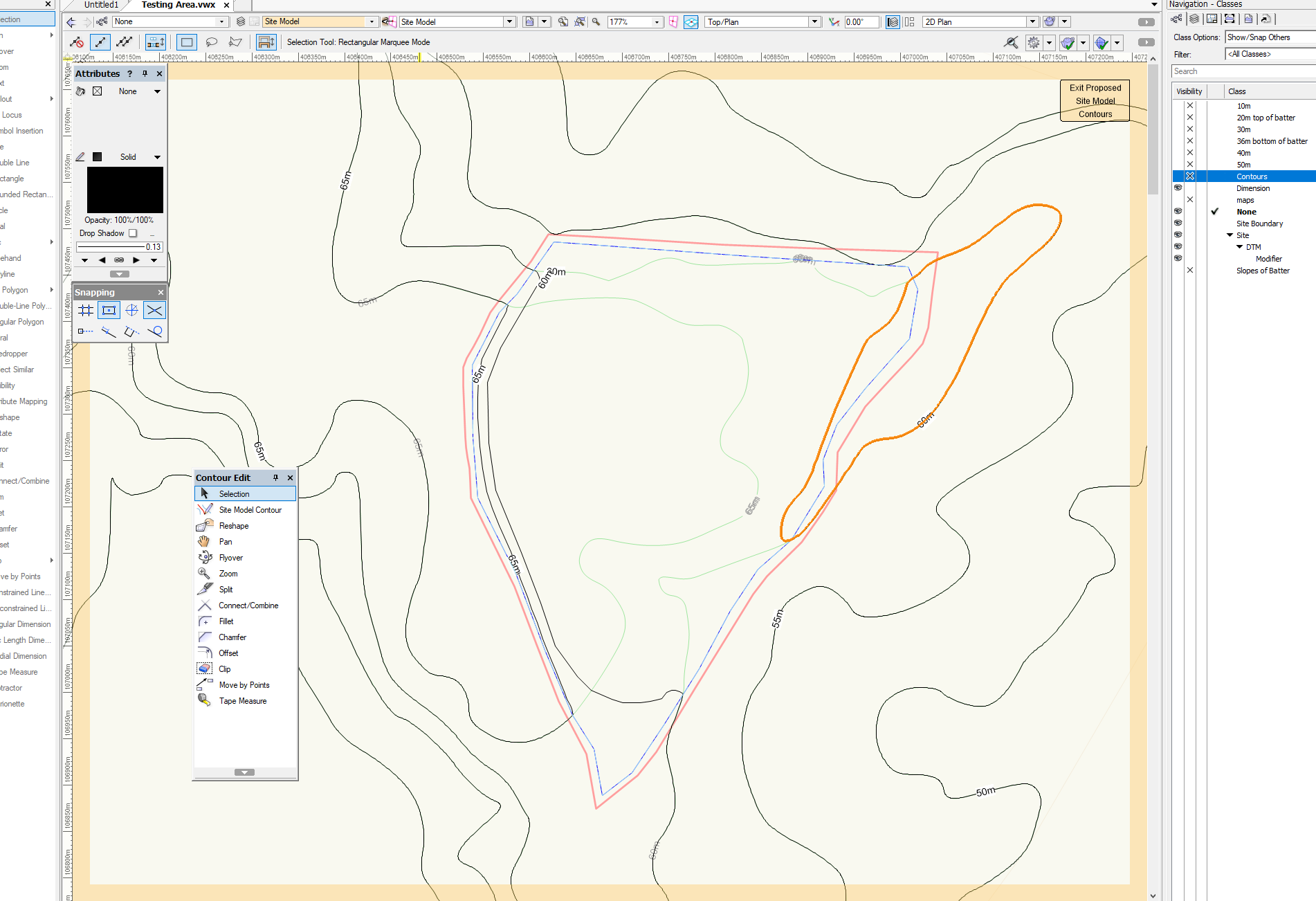
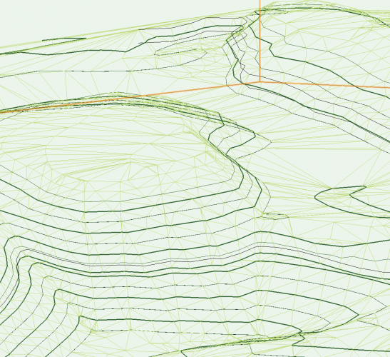
@Benson Shaw I am now having the same issues with my propsed contours (as earlier it was just the existing set of contours). This time however it has gone a bit haywire. In the image named 'capture', you can see that I have edited the contours to create a hole like feature. However, when I finished moving the contours in the edit proposed contours screen and it then calculates the new model, the contours are all over the shop at crazy angles. The only thing that I can think of is that... 1. The contours are large and extend outside the grade limit, therefore I may need to make a larger grade limit around the whole area. 2. I have not used enough vertex / verticies when constructing the new contours and therefore the model doesnt have enough to work with. Cheers.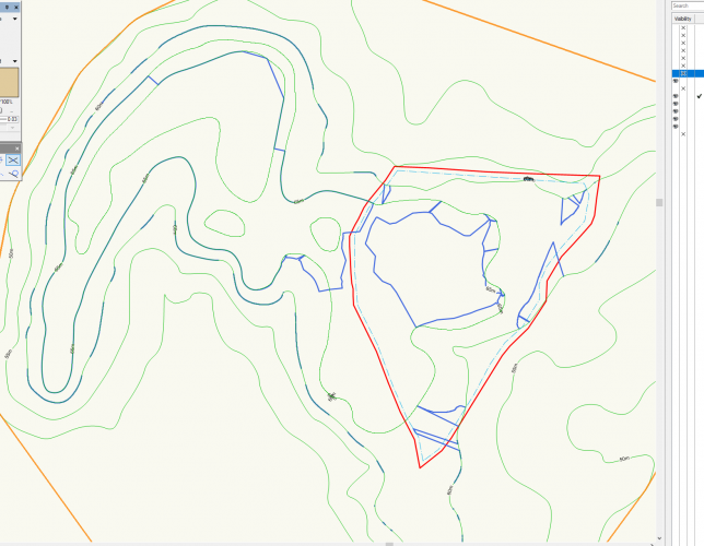

-
@Benson Shaw Hi Benson, Thanks for the reply, I do actually have 2019 I just haven't got around to updating my signature (can't remember how, i'll have a look now). Cheers! Joe
-
Hi all, I have some LiDAR data that I am attempting to play around with and create a site model. The data is free from the Environment Agency (UK) and I have it as a DXF at 1m resolution. Unfortunately, due to the size of the field, and the density of 1 3D loci per metre, there are a mere... 782,864 3D Loci on my drawing. This is causing an insane amount of lag for me! I note that there is a simplify 3D polygon command, but as these are loci and not polygons, I am assuming that this does not work for this data type. Is there any other approach I can take to make the data more manageable? Any ideas would be appreciated. Thanks Joe
-
Site Model Contours Being Modelled Incorrectly
Jainsworth replied to Jainsworth's question in Troubleshooting
@Benson Shaw Thanks for this, helped a lot. I managed to get them to fit, although I had to use a ludicrous number of 3D loci to get it to actually site on the contours (aka surround the 70m island features with 68m loci in a circle. Therefore the space between the contours will be somewhat flat, but that should not be a problem for this exercise. Thanks! Joe -
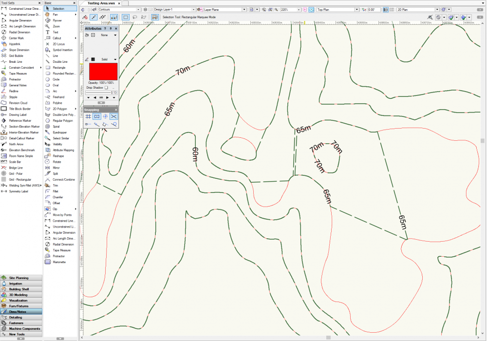
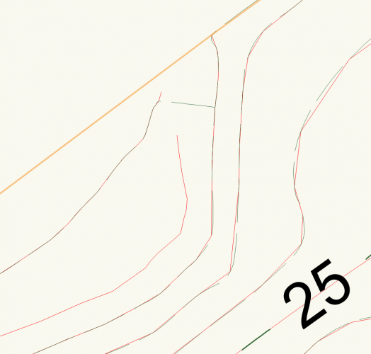
Hi all, I am having an issue with my site model. It is a simple model with only 7 3D polygons that have been used to create site model contours. Unfortunately, the model is skipping some of the contours and drawing straight lines instead (see image attached). The red lines are the 3D polys I have used, and the dashed green is the models interpretation. Is this simply the inherent VW 2019 model creation process doing this due to a lack of data, or is it a setting / something I can rectify? Any ideas would be great! Thanks Joe
-
Selection of questions across a variety of topics
Jainsworth replied to Jainsworth's question in Troubleshooting
@Gadzooks Thanks for the info! Generally how I work in these scenarios is I try those sources first when I encounter something that either I don't understand or can't work etc. So hopefully my questions are not addressed in any vids or tutorials! Anyway, here are my questions if you have any answers! Thanks again! 1. Is it possible to customise the colouration of a site model beyond a maximum and minimum colour? (e.g. above 50m in height the model will become red). So far my workaround has been to copy and paste the model, and limit the Z values on each so that one model ends where another starts vertically. 2. Can you fill in the clip cube so it gives an interior of the site model? Normally the clip cube shows the interior of the site as hollow. 3. Can I select one particular aspect of the site model and alter it? In my case this would be the transparency of for example just the surface on the top and not the sides/underneath etc. I have struggled with making the site model see through with a lot of trial and error. 4. Is the best way to remove site modifiers and their associated effects to remove them from the specially created modifiers class? 5. Is it possible to apply a 3D line across the site model surface? Another way to put this is can you drape a shape over the site model. This would also be useful for property boundary feature. 6. Can you add a water level to the site model? Thanks again and if you can provide any answers that would be great 😁 Jainsworth -
Hello everyone, I have a bunch of questions relating to various aspects of VW (mainly site models related). What would be the best way to get some answers? Post here as a series of bullets or numbered lines and then if anyone knows the answer they can simply pick a question and answer? Would appreciate any suggestions. Most of the answers are probably just 'Yes' and 'No' 🤣 Thanks Joe
-
Hi P Retondo, I'm a little confused as to what you are saying with the contours. When you create site modifiers you choose the type of modifier, and that includes pads, and also contours. So would that not mean that contours are a type of modifier? I actually just solved my problem - turned out that I had put an extra contours underneath the original so there were 2 contours on top of each other, and the model was trying to compute them both! I deleted the original and all was well. Joe
-
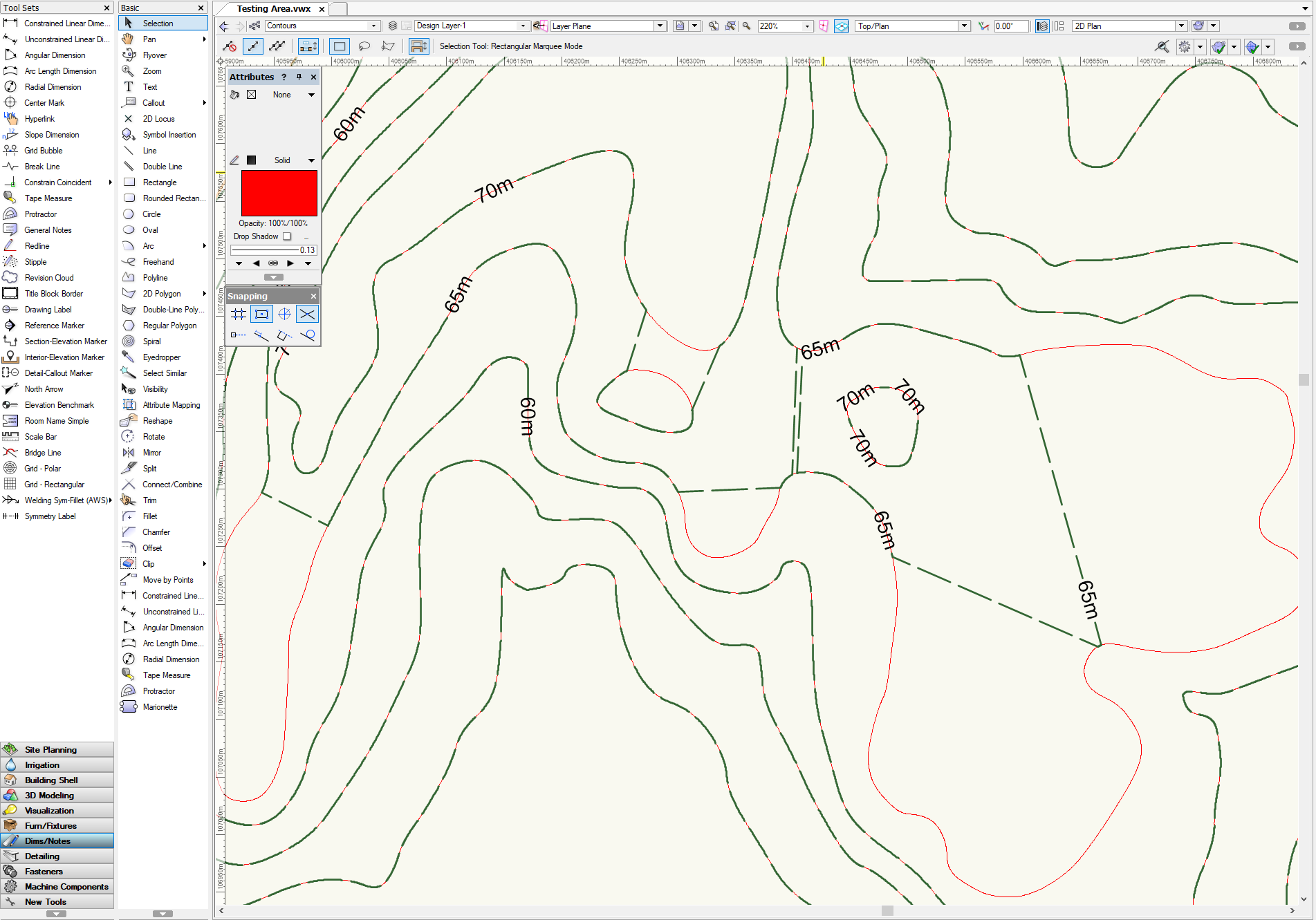
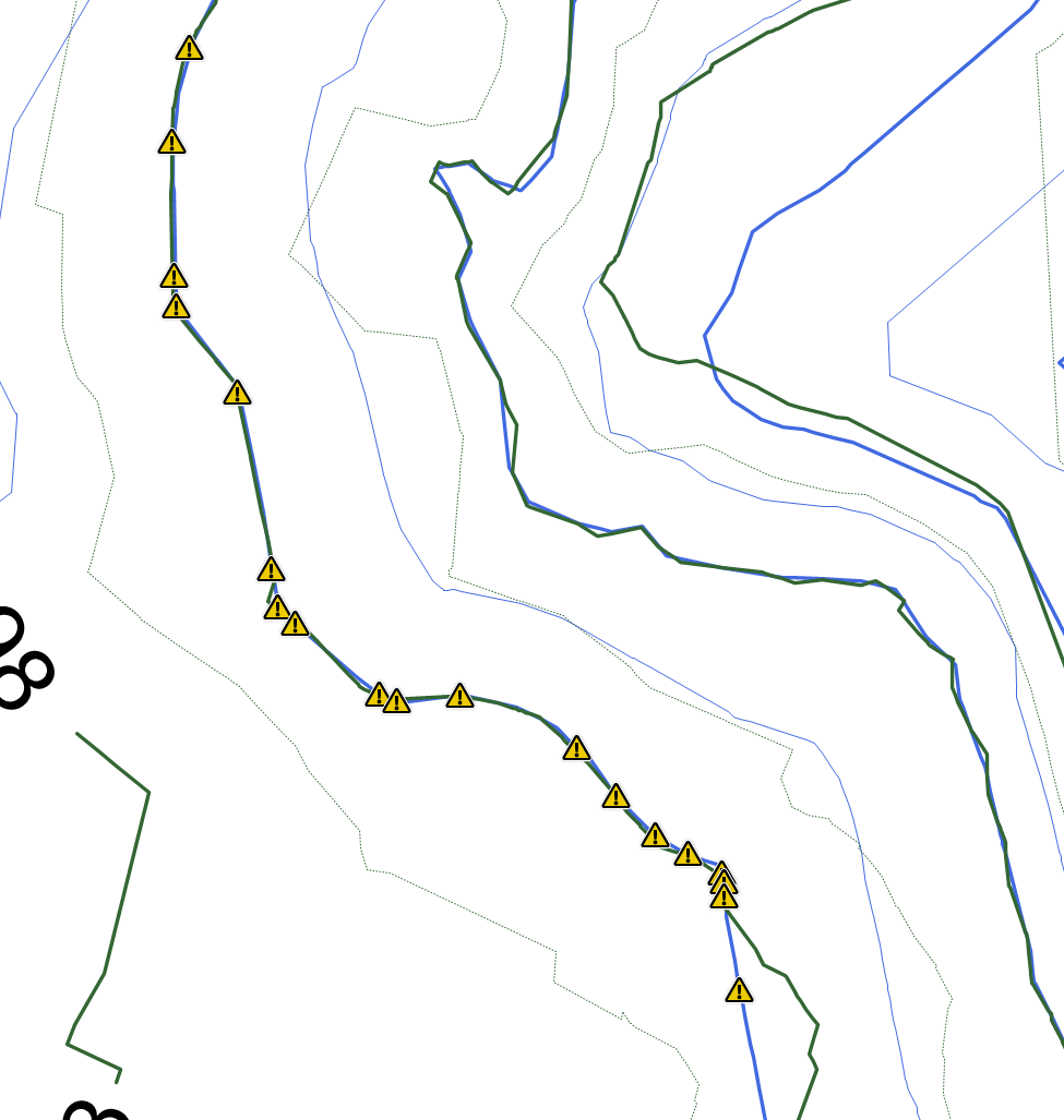
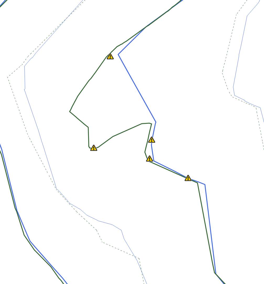
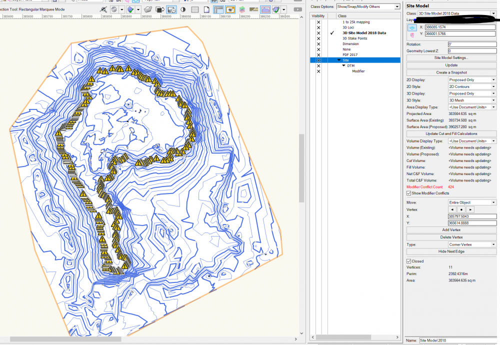
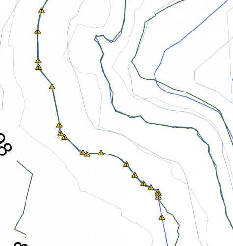
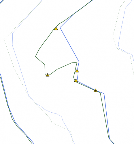
Hello all, I have been working a site model for a quarry. I have two sets of survey data, a topographical survey taken in 2017 in PDF form, and a topo survey from 2018 of the same site in DWG form. I turned the DWG into a site model, and have added in site modifiers of the 2017 data by adding stake points and contours, so that I can compare the two surveys to see how the quarry has changed. I have encountered an issue with a particular contour in the site modifiers, and this contour has flagged up 424 modifier conflicts. I cannot get my head around why only this contour has the problems, and upon clicking the warning triangle it states 'Pads Intersect', however, I have not used any pads, only contours and stake points. Does anybody have any suggestions as to why this is happening? As you can see from the zoomed in images, the modifier conflict warnings are not actually sat on top of 'crossovers' and you can see from other contours that these are not problems. I have attached pictures to help, with the zoomed out image showing only the proposed contours, and the zoomed in showing both (green and blue) proposed and existing. Thanks Joe
-
Title Block and Border Vectorworks 2018
Jainsworth replied to Jainsworth's question in Troubleshooting
Thank you Jim -
Hello, I am looking at setting up a title block and border to ues at the company I work for, as at the moment things like this are done manually for each file. It would appear that all of the guides I have been using online are not correct or are out of date. I am guessing that the feature was overhauled in VW 2018. Does anybody have any recommendations regarding guides / videos in this area? Thanks Joe
-
Hi, I am creating a site model off some basic contour data that I drew myself from a PDF document. However, after creating the model, it appears that VW is creating a couple of it's own contour layouts and ignoring a portion of a contour completely (see attached - red line is 3D polygon, green is site model contour). Is there any way to correct this? I have tried editing the existing contours using the option but there doesnt appear to be any difference. Thanks Joe
-
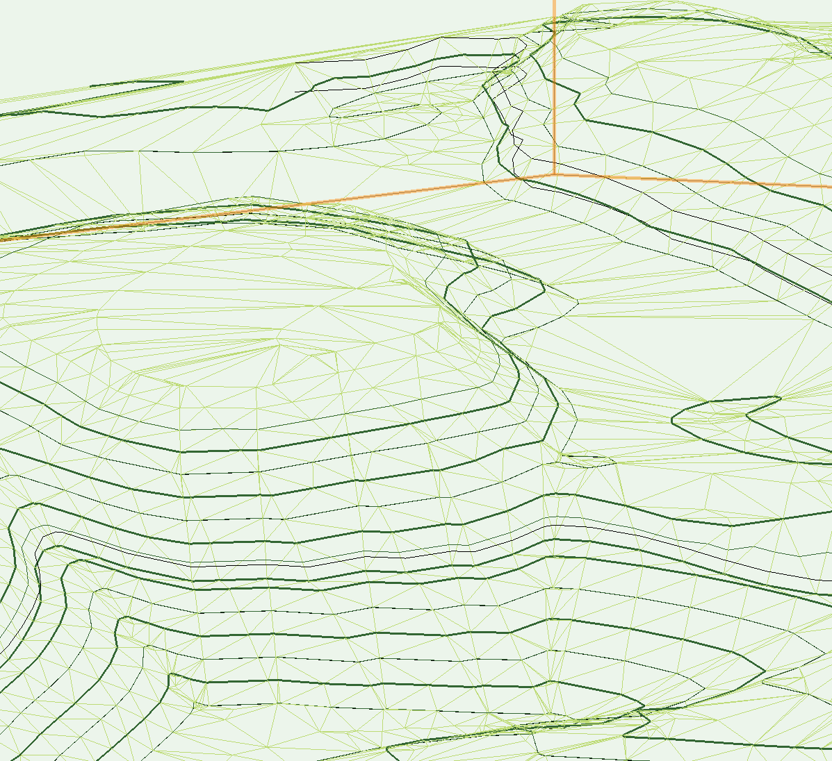
Hi all, I have been experimenting with creating a site model of a quarry. It is quite a large dataset contour wise, and I successfully converted the 2D polys to 3D. When applying a site model however, it appers as a sort of mesh / spider web. Any suggestions? On the right hand side, I can see that the visual element is set to 3D mesh. Using Landmark 2018. Thanks Joe
-
Opening multiple files in separate windows in VW 2018
Jainsworth replied to Jainsworth's question in Troubleshooting
Hi Alan, I did try that, however my 2nd monitor is not the same resolution so it doesnt work as well as yours! Thanks Joe -
Opening multiple files in separate windows in VW 2018
Jainsworth replied to Jainsworth's question in Troubleshooting
@MullinRJ I have just got off the phone with VW UK, and they confirmed that it's not currently possible on PC. Maybe next time... Joe -
Opening multiple files in separate windows in VW 2018
Jainsworth posted a question in Troubleshooting
Hello, This is my first post as a VW Forum member, so thanks for reading! My query is likely a simple one - I have 2 PC monitors, and would like to use one screen for one file, and another screen for another file, in order to compare what is going on as I am working. However, I cannot seem to find the setting to allow this, and have looked around the 'window' settings and have checked the workspace settings for things related to docking of windows. Any advice? Thanks