


jcogdell
-
Posts
974 -
Joined
-
Last visited
Content Type
Profiles
Forums
Events
Articles
Marionette
Store
Posts posted by jcogdell
-
-
The lighting pipe tool has not been removed. If it is missing from your rigging tool-set you can add it back in by going to
Tools-Workspaces-edit current workspace
once inside the workspace editor open the tools tab
expand the spotlight tools on the right, scroll down till the lighting pipe tool is visible and then drag and drop it into the tool palette of your choice on the left (typically lighting or rigging)
This will add it to the tool-set of your choice
-
Also you can save your numbering settings as a template to reuse in other documents and it can be used on any object in Spotlight that has a data record, such as trusses, hoists etc.
-
Hi Robert
The Tomcat truss is grey because Tomcat has not provided us with the background data necessary for Braceworks. When ever we have a truss type that is missing the data for Braceworks calculations (including trusses created with the old straight truss tool), a default set of data is applied and the heat map function will not work with that element to highlight this.
-
Hi Allan
These features are in Spotlight 2019.
You can find the hoist legend function in Spotlight-reports-crate hoist symbol key will put a hoist legend on your plan
Hoist reports are created in the same place and can placed on your plan the same as any other report or worksheet.
Go to Spotlight-Rigging-Replace truss and use the export function and it will create a truss report with what is needed for each truss system. In the same interface you can access the truss inventory where you can export your truss inventory totals (use vs in stock) as a .csv file
You can also use the worksheets to prepare truss lists, there was a recent forum thread related to this, I've linked it below for you to look at.
-
 1
1
-
-
Hi Alan
If you need actual lessons I would suggest getting into contact with Peter Neufield at OzCAD. He is very experienced and can provide both support and training.
gruße
Jesse
-
When you run your on pc console and Vision on the same computer they should connect automatically, as long as both are configured for the same control protocol (Artnet, SACN, MA NET), also MA Net 2 will work without a security dongle in this scenario as well ( dongle is only required for physical consoles, as far as I remember).
Regarding the 2nd monitor if you are using one computer for both Vision and your on PC, it makes life a lot easier.
-
1
-
-
Hi Suni
Another tip is to use a second monitor if you can, so Vision is on one and your on pc console software is on the other, makes it much easier.
Regarding Artnet or any of the other protocols the make sure that both vision and the console software are set to use the same protocol, it should then connect automatically.
hope this helps
Jesse
-
1
-
-
Just to clarify you set the basic position of the 3d label legend elements when that legend is first created. This is done in the label legend manager in a similar way to the old 2D label legend workflow ie pick what you want to display (for 2D and/or 3D) and then position the labels round your fixture in 2D and in 3D.
The drag and drop is for when you have the legend obscured by another fixture or object. Unless your plan is very crowded (fixture counts in the 1000s +) you should only have to edit a few in any given model as long as the label legend was properly prepared.
-
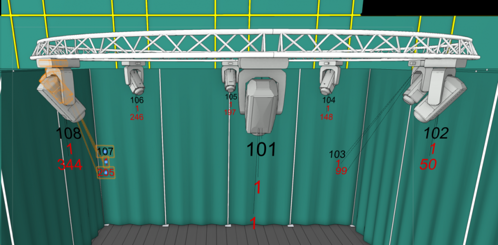
@Gabriel Chan Spotlight label legends received an overhaul in 2019. The 3D label legends can now be orientated in any direction and re positioned by selecting and dragging to where ever you would like them in relation to the fixture. A leader line has been included to show which fixture the legend is associated with. see below
-
Is it just that you are receiving the warning about the symbol containing 3D info only? if so just go ahead with the conversion, the only thing that will not be displayed is the simplified view of the truss objects, the hanging position will function as normal. If that is not the issue please upload a copy of your save file and I will take a look, as currently it seems to be working fine for me (2019 sp2).
gruße
Jesse
-
Hi Hayden
You are doing nothing wrong! Scott is correct that the blue symbol is part of Braceworks.
It is called a Truss Cross connection and represents where 2 structural objects, such as trusses or pipes, are connected to allow the transmission of forces for Braceworks calculations, you can define the connection as solid or flexible. 2 real world examples of this would be using scaff clamps/cheeseboroughs to attach an out-rig pipe to a truss (rigid connection) or hanging a perpendicular 3 chord truss directly under a 4 chord truss using a steelflex (flexible connection).
There is a problem that your example picture highlights.The problem is that spigoted corner blocks should not be able to connect together flush without space for the female side of the connection or an adapter. The truss cross connection is the correct behavior for the vertical connection but it should not be possible create the horizontal connection between the 2 corner blocks shown in the picture.
I will open a bug report, thanks for bringing this to my attention
gruße
Jesse
-
1
-
-
Hi Cam
Thanks for the bug reports, I have put both into our system.
gruße
Jesse
-
Hi Scot
Nice catch.
I tried this with Peters own file earlier and also again just now with yours Scot and I think I know what is going on.
In Peters original file he has used the old straight truss tool to create his truss, where as Scot you used the new insert truss tool with a section of Thomas truss.
The truss created by the old create truss tool does not seem to allow the connection from pipe down to truss. I just tested it again by starting from scratch using the old create truss tool and it is definitely causing the problem. I'll start a bug report
Cheers
Jesse
-
1
-
-
It was fairly common when I first started here in Europe in the mid 90's as well. If I am remembering correctly there were a couple of nasty accidents where Aluminum pipes got used instead of steal this and led to the current standards.
However as you say there are a lot of venues around the world that use the fixed grid scenario and I agree that we must be able to provide a solution for this with Braceworks. I'll start a feature enhancement request to add this.
Gruße
Jesse
-
One of my previous employers ran into a really special example in China. He was doing site visits looking for a venue for a client and visited a venue in southern China. The venue was a theater style venue, in a rural area and from the front of house side looked pretty good. It had a huge parcan rig which being as it was around 2013 or so he thought, not ideal but it's china and this is better than I expected. He then made the mistake of looking at the at the lighting console and found out it was self built by the venue's 'electrician', it consisted of a table covered in rubber matting with 2 strips of wood holding a series of bare wires a few centimeters above it and a pair of hammer style 'drum sticks' with cables attached. the bare wires were the live wires and 'drums sticks' had the neutrals attached. The house 'electrician' very proudly gave a demonstration complete with sparks flying everywhere, apparently there was more light coming from the console back stage than came out of the parcans.
Needless to say my ex employer rapidly made his excuses and left as fast as he could. Some of what happens in China and the ex soviet republics has to be seen to be believed.
-
Hi Peter
I'm pretty sure this was specifically designed not to allow drops from pipes to trusses due to German / EU rigging standards.
Moritz could confirm one way or the other.
Gruße
Jesse
-
Hi ubybc
The Source 4 14deg is already in our fixture library, look in the Ent Lighting Instruments-ETC-Source 4 or ETC-Source 4 750w folders in the resource manager
I'll pass the other fixtures on my colleagues.
-
Hi Tom
From your description you are trying to hang the upper (or pre-rig) truss using the 'insert connection' tool, this will not work as it is designed only to connect between trusses and/or pipes. To hang your pre-rig truss correctly (for braceworks calculations) there are a number of possible methods,
The quickest is to use the 'insert hoist tool', attach the motors to the truss and then adjust the high hook field in the OIP to match the height of your house rigging point
The next is to right click on the 'insert hoist tool' and select 'insert deadhang' option, attach the deadhangs to your truss and adjust the chain length and shorten field in the OIP to the desired heights.
In both the above methods it is not necessary to attach the hoist or deadhang to a house rigging point and the newton loads will be displayed both in the OIP and on the hoist or deadhang label
A third way is to use the 'insert bridle tool', for this you have to first either insert house rigging points or structural members using the appropriate tool and then go into the bridle preferences in the spotlight rigging menu to tell the tool which it should attach to. Next select the 'insert bridle tool' and select the type of bridle you want to insert (single/ deadhang, 2 leg, 3leg, etc) then insert your bridles. The advantage of this last method is that the bridle tool will generate diagrams of the bridles and associated material lists for your rigging team, both saving time on the get in day and helping with the pack list planning.
If you need any further help give me a shout using Slack or by email and we can share a screen, I am based in Berlin so the time difference is not a big problem.
gruße
Jesse
-
2
-
-
no problem
To clarify I was wondering if it is possible to make custom multi cables that use more than 6 circuits and function correctly with the assign circuits and breakout label tools?
The reason I am asking is that there are many cases in the entertainments industry where the user would want to be able model multi-core cable types with more than 6 circuits, one example is that here in Europe most countries use a 6 circuit standard for HAN-16 multi-core cables however in the Netherlands they use an 8 circuit standard for the same HAN-16 cable type (they also use a different Live/neutral phasing on the pins in the connector itself but that is another whole problem and not relevant here!)
If I am understanding your description above correctly I would have to use the plugin manager to add both new connector/breakout types to the appropriate parameters choices lists, then add new parameters for the extra circuits to the tools and lastly edit or create new breakout labels that reference the new parameters. I would then also have to repeat these changes every time a new service pack update is released. Please correct me if I am wrong
-
Hi
Cool that you found a solution, I hadn't found this when I looked previously. I have included the link for other interested users below
@ Sam, could you post either a quick description of how to make the custom cable types here for other interested users or a link if it has been previously covered?
Cheers
-
Hi Michael
There are 2 ways to this that I have found,
Method 1: to directly edit the point load or distributed point load symbol in your document and right click on the symbol. Then select "edit 2d component" and in the edit screen select the part you wish to edit, change the color then exit the symbol. The problem here is that you will have to edit each symbol individually as the symbol does not appear as a resource in the resource manager.
Method 2: would be change the color for the audio hoist symbols to match the color set in the load tools. To do this use the resource manager to find the audio hoist symbol or symbols in your current document. Staying inside the resource manager use the same editing process as in method one and save the hoist symbol. This will then update all the instances of this symbol in your current document. If you want to use this symbol for future plans it can be exported to your favorites or another .vwx file by right clicking on your edited symbol in the resource manger and using the export command.
Jesse
-
Hi
Sam is correct in that you cannot add a new cable type.
A workaround would be to create separate layers and classes for the cable types you want to create, then when you insert your cables, go into the tool preferences (for that particular tool) give it an appropriate cable run ID, color etc and then use the "User Fields" to label as the cable type you want and connector/breakout type. You then set up your cable worksheet for that cable type to display the user fields and not the cable type or connector fields and to sort by the appropriate layer. This will at least give you the cable lengths and totals.
Hope this helps
-
Hi Jim
The tip with the navigation graphics seems to have fixed the problem. Thank you for the fast response, I'm just a bit shocked that I missed this.
Thanks again
Jesse
-
Hi All
I'm having a huge problem with converting my 2016 plan to 2018. The plan imports without error messages but will not display any of the 600+ fixtures. Strangely enough changing between visibilities sometimes briefly displays the fixtures but the moment I try to do anything with the plan they disappear again. I've tried importing the file new several times inbetween updating the plan due to the current rebuild but it doesn't seem to help. It consistantly only displays the fixtures that were visible on the active view at the last save point, and then when I switch views (floor to roof or viceversa) it will not display the rest of the fixtures. I've checked the visibilities etc in the back ground and unless I am missing something fundamental I can't figure out what is wrong.
Any advice or help would be appriciated.
Jesse

Inlination oef a truss system for calculation
in Braceworks
Posted
The way to do this is to select your truss (all connected sections that you wish to do this with) and toggle the draw 3D only option on in the Object Info Pane
next group select the trusses and lights, change to the appropriate 3D view (front for example) select the rotate tool from the basic tool palette and use it to rotate the selected trusses and lights to the angle you want.
Changing the angle of the trusses and attached lights will break the connections for rigging hoists/deadhangs/bridles so you will then need to re-attach them before you can run any Braceworks calculations.