LeeElston
-
Posts
160 -
Joined
-
Last visited
Content Type
Profiles
Forums
Events
Articles
Marionette
Store
Everything posted by LeeElston
-
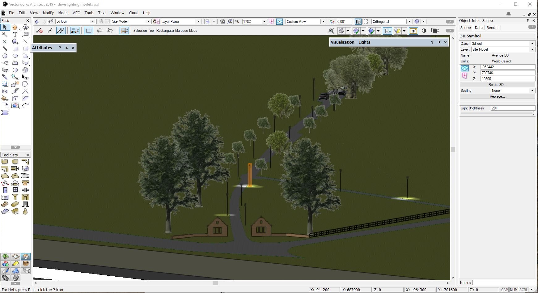
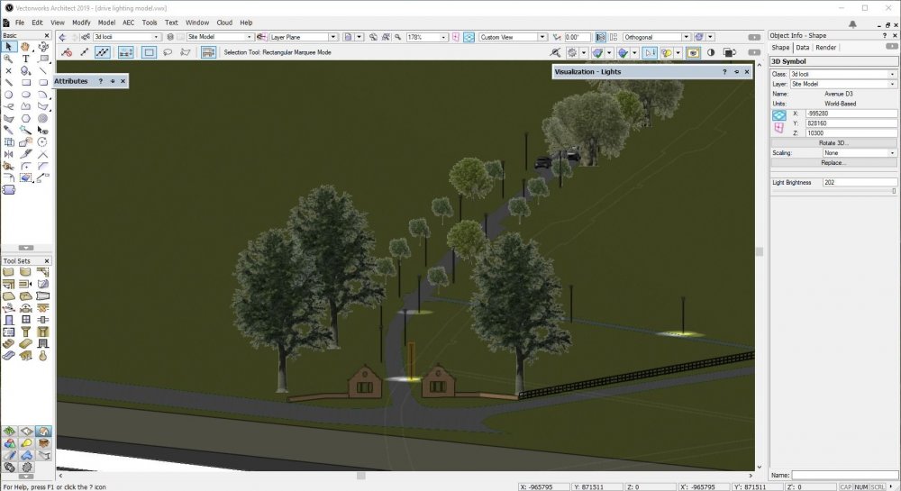
I have created an site model of a long driveway with lighting columns as symbols spaced along it, but when I view in open GL, only 2 of the lights are fully on 'on' at a time, with a third showing reduced lighting... All of the symbols are the same and the light objects within are switched on. To Make a different light 'come on' I have to increase the brightness slightly, but then another light goes off somewhere else.... I enclose a couple of screenshots to demonstrate. There is also a heliodon object but this is turned down so you can see the layout and the light spread better. Is this a setting or a limitation of my graphics? Thanks in advance.

-
Thanks Jonathan
-
How do I select which point on an object follows the path? I'm sure I saw it on a tutorial video somewhere but not the one linked in the Vectorworks Help.. Any pointers appreciated
-
Is there any way the wall tool can be programmed to return internal plaster or external render into reveals? It knows the window is there andthe size of the components so I wouldn't think it was too difficult... 🙂
-
Is there a way of setting the wall tool to only draw walls of a length to suit the module of the material in the external face. Thinking of brickwork where 112.5/225mm increments are the norm, with a corresponding perpend addition/loss at corners. Can this then be carried into the window widths?... In the Jamb and sash menu of the Window preferences schedule there is a 'Masonry Module' box, but I can't find any in depth guidance on what this does.... Thanks in advance
-
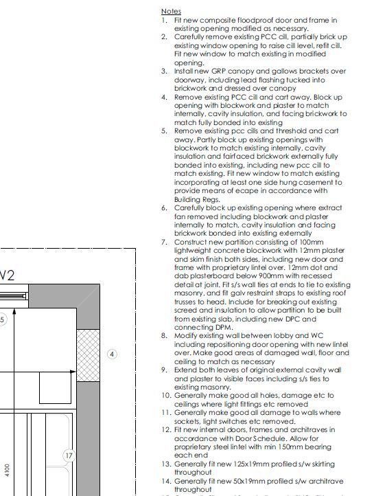
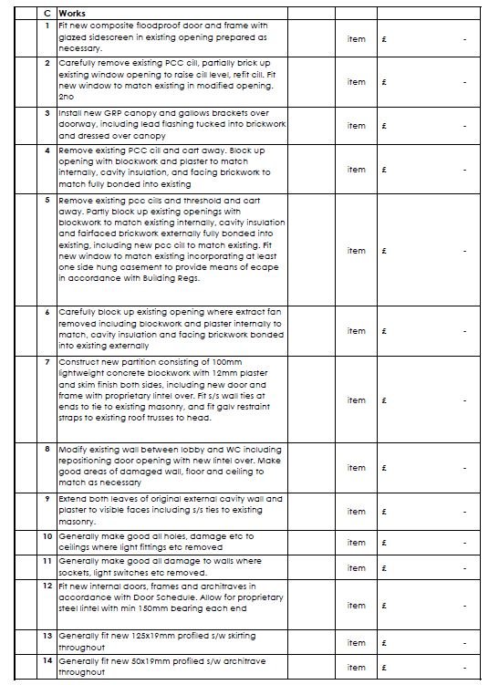
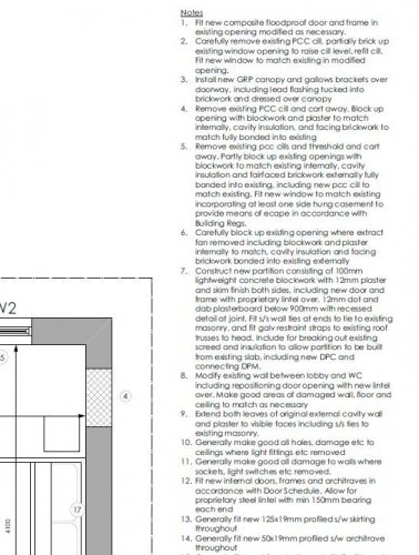
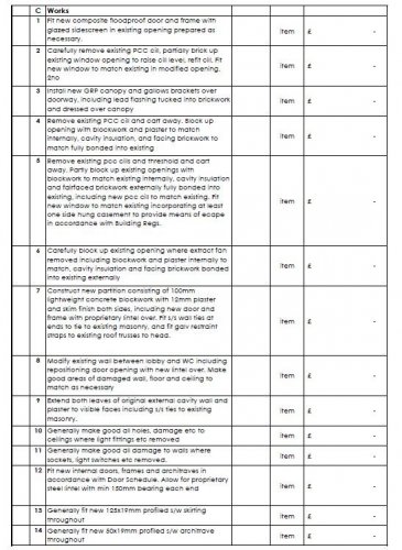
When adding notes to a drawing using the callout tool, you create a database of job specific notes. Is it possible to create a worksheet/spreadsheet using these notes? Ideally I want to create a schedule of works that identically matches the notes on a drawing without having to cut and paste to Excel.... Any tips appreciated. Screenshots show drawing notes and spreadsheet I want to recreate
-
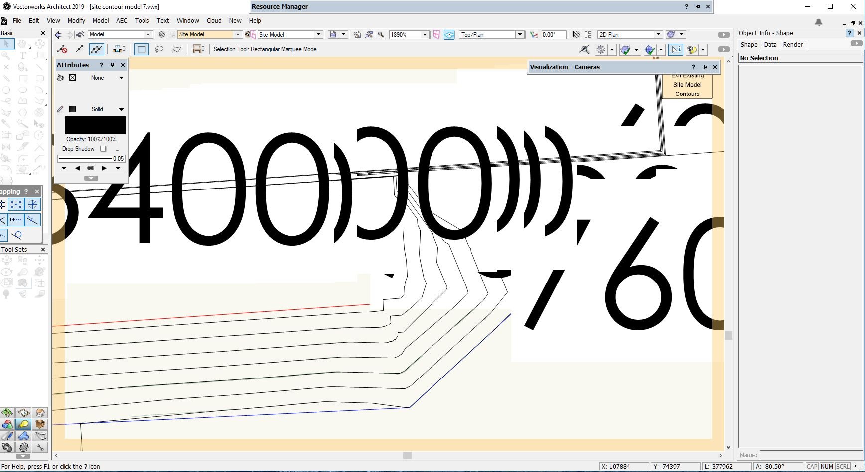
When I enter the site model to edit contours, the contour labels appear, even though they are turned off in the Site Model Settings... Because of the location they obliterate the contour line I'm trying to edit so I cant see it... Is there a way of turning the labels off completely, or do I need to see if the software can be upgraded?.. Cheers

-
I recently lost an afternoons work because I had a crash, and I had somehow accidentally and unknowingly turned off autosave. Just thought it might be an idea to add a padlock to the 'autosave' tickbox so this can't be done accidentally......
- 1 reply
-
- 1
-

-
I have the same issue so if anyone knows the solution it would be appreciated.. Back to 2018 til then....
-
Since installing 2018, the line tool keeps locking, in that when creating a new line and using the tab key to enter the box to type in the length, the current length is highlighted blue, but can't be edited. Even when a line has been created in this state, it can't be edited even using the object info box. It does work for a while if I restart Vectorworks, but after a while invariably starts to freeze again. (This also applies to the rectangle tool, and maybe more that I haven't used since installing 2018)Anyone else experiencing this or am I inadvertently changing a setting with an unwanted keystroke somewhere...