


LeeElston
-
Posts
160 -
Joined
-
Last visited
Content Type
Profiles
Forums
Events
Articles
Marionette
Store
Posts posted by LeeElston
-
-
Can we have a facility to identify which point on the profile is the origin for the extrusion.. At the moment it uses the centre point of the profile (unless I am missing a setting somewhere...)
-
I'm drawing the HVAC system for a scheme and the standard tools allow for circular ductwork, transition pieces etc, but the splitter tool only seems to do rectangular... Am I missing a setting somewhere?...
-
Thanks... Just seems to have been the number of perspective viewports I had created...
-
I have been getting some files which are growing to an unwieldy size, despite not intentionally having huge amounts of information, or being large buildings. One in particular has grown to 473MB and struggles with crashing when rendering in Open GL, or creating new section viewports!! Obviously I can't upload it for tech to look at as there is a file size limit. Any users had similar issues and found a glaring settings change that can be made to shrink the files. I have asked if a future webinar can cover this subject but in the mean time.... heres hoping
-
I have a couple of curved walls which while appearing curved in a top/Plan view in a viewport, straighten out in the same viewport if the projection is changed and they are rendered in Open GL, either as a Top view or perspective. The sheet is set at 600 dpi and the viewport has High detail in the background render options, and I have changed the crease angle, all to no avail... Any ideas?

-
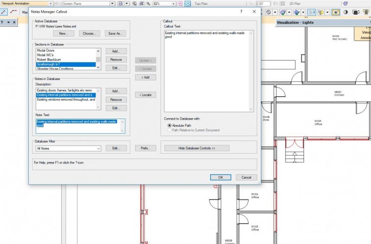
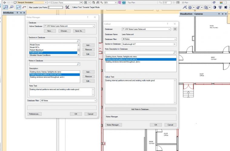
You can still do it but it doesn't seem as simple and intuitive as it was before as you have to find the new note in the list to attach... If you have a lot of notes starting 'Remove existing....' or similar it is a pain....
-
Don't know if it's intentional but having the Notes manager and the Callout windows seperate rather than in the same location as they were previously is a definite backward step...Seems much more difficult to create notes now. Am I doing something wrong?
-
 1
1
-
-
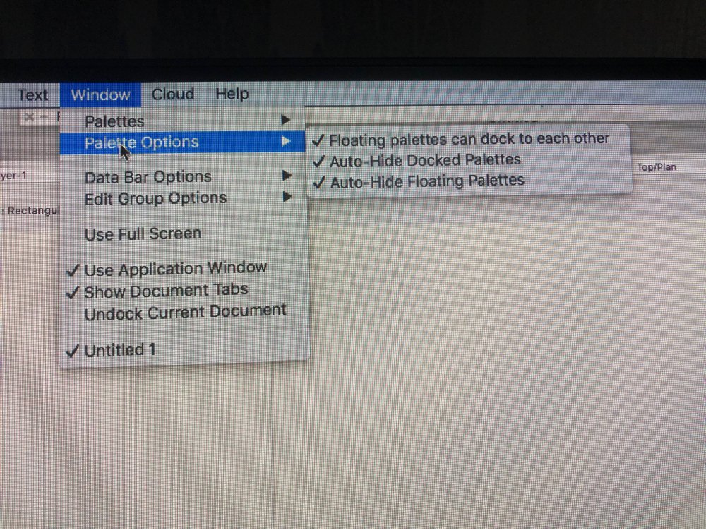
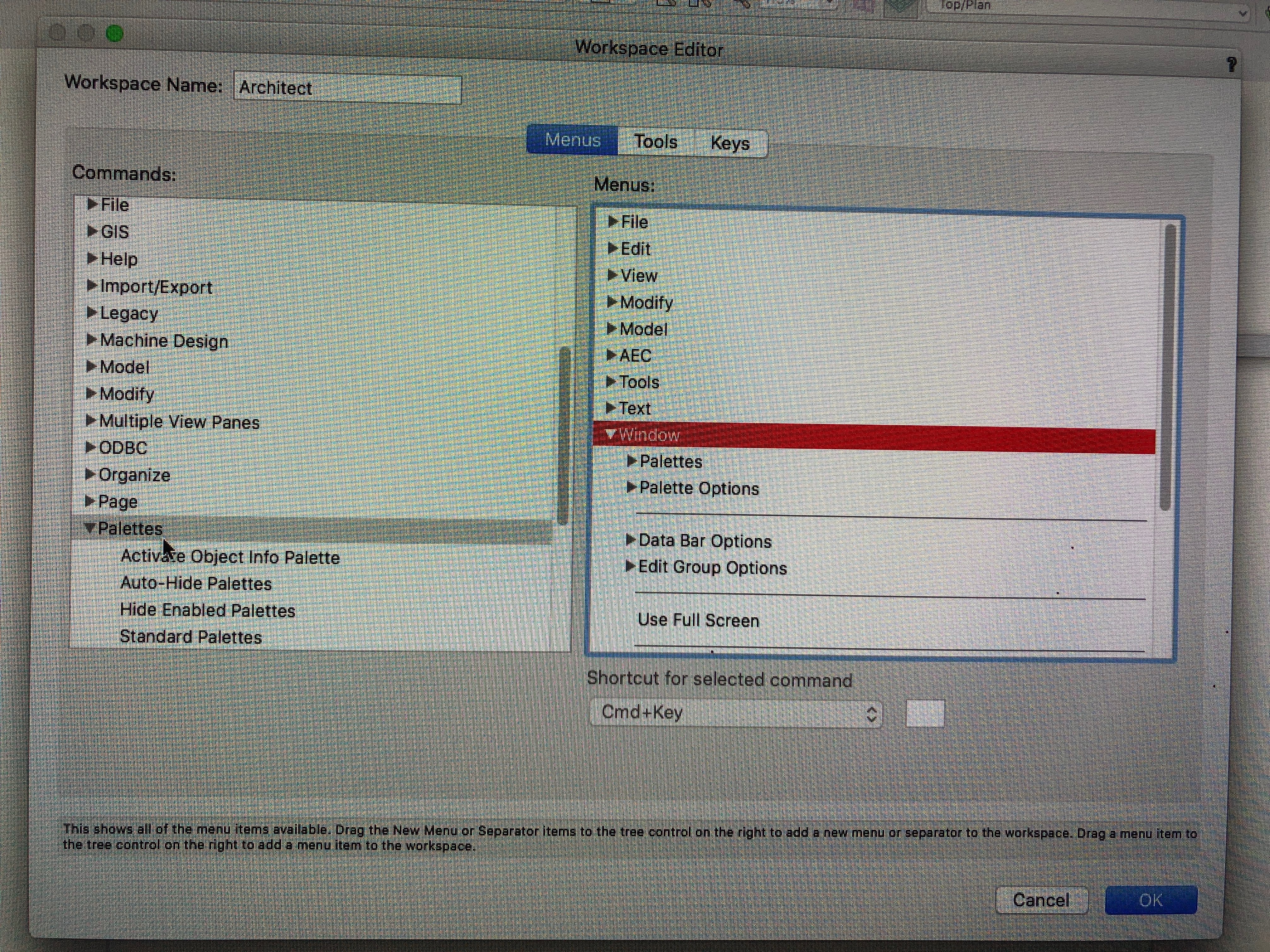
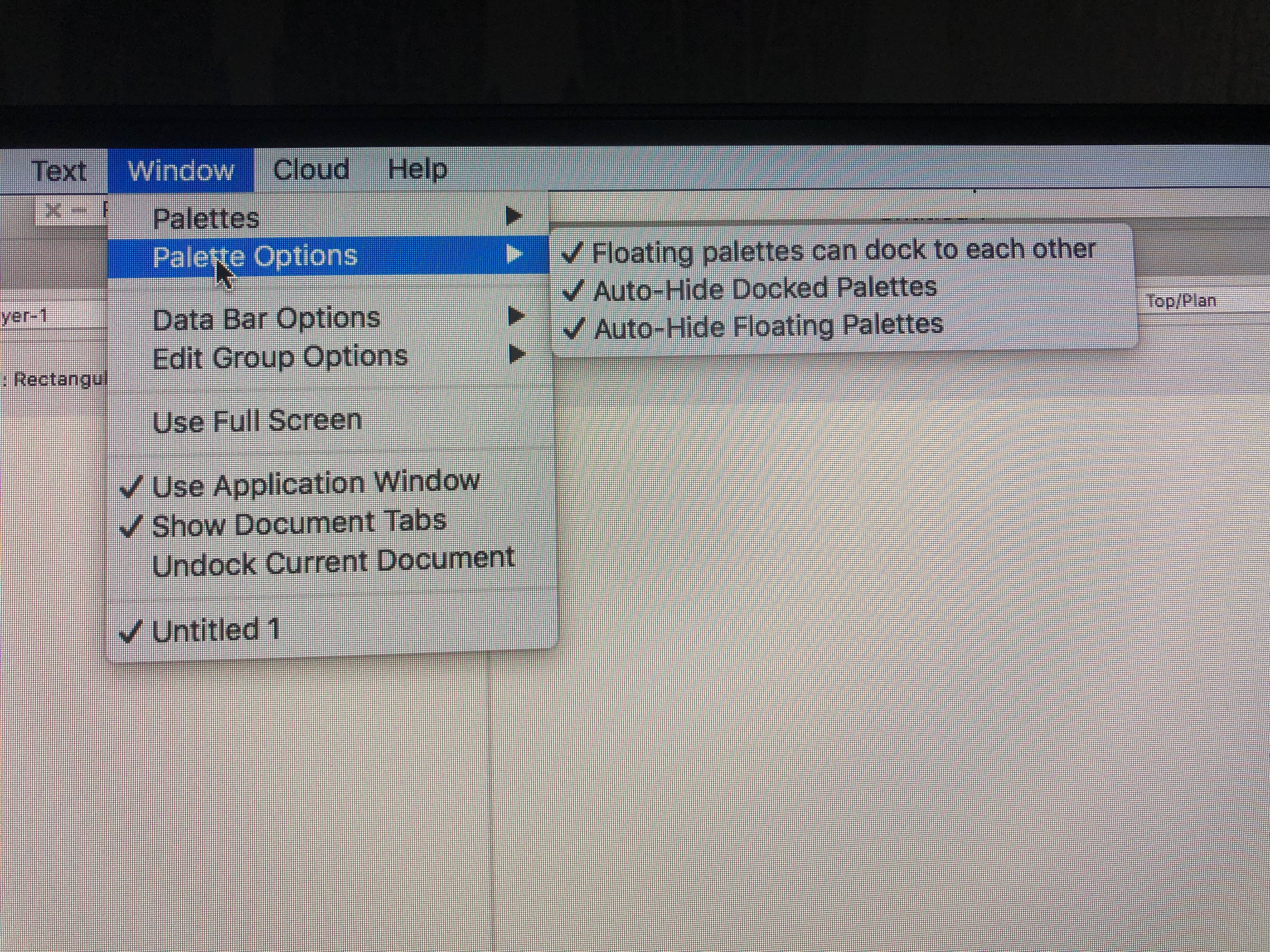
Think there must be a Mac vs windows difference... On the Mac there is an additional 'Palette options' menu which I can;'t find on the PC. I have also seen reference to 'borders'?
The additional menu seems to allow docked palettes to each side of the screen to auto hide...

-
I don't have the above feature in the Window>palettes menu in the workspace I have migrated from VW2019 to VW2020. I seem to recall in the past I hade to remove persoanl workspace to get the BIM option to show, but can't recall how to do this...
I have looked in the 'Edit current Workspace' feature and looked for the 'Auto hide floating palettes' in the 'menus' tab but it isn't under the 'palettes' command where I would expect it to be...
Any suggestions appreciated
-
I'm trying to create a symbol of a standard house type to import into a site model. The house type has been created in a file using storeys, then duplicated and a symbol created in the same file. However during the creation of the symbol process the first floor slab seems to be getting fixed onto the ground floor plane, and even if I try to edit the 3d component of the symbol, it won't allow me to change the level. It is at the correct level in the model, just drops a story when I convert to a symbol. I have checked the 'story aware' box in the preferences. I do get a 'illegal objects have been selected' message when creating the symbol but it doesn't seem to highlight which element this refers to....
Any pointers to my mistakes would be appreciated....
-
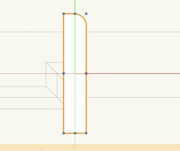
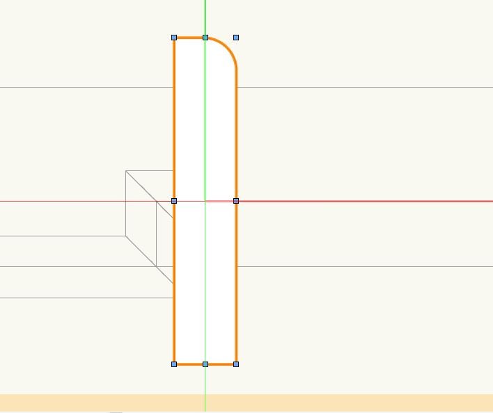
In order to activate(highlight) the face which is to be sub-divided, I have to open the push/pull:subface mode, then select the line and hit delete ( I found this out by chance) before the face becomes active.. I don't think the delete key should be involved in any of the 'Getting Started' guides or webinars I have seen so I have changed a setting somewhere... Any ideas how to revert to normal mode?
On the back of this, is there not a way to draw the line as a ridge and just drag it up to give a block model. The only way I have found is by using the Taper face tool.... Seems very basic not to be a tool for this if I am missing it.
.thumb.png.c12c447f1038bc2ddf7d9a1fc095d98b.png)
-
Sometimes (I know occassional problems are the worst!) when I have more than one drawing file open at the same time, the class list doesn't update if I go from one file to the other. As can be seen in the enclosed screenshot, the list of classes available in the OIP class dropdown box is different to that in the Navigation list of the file I'm working in.... I have to keep closing the files and reopening to reset. Is this just me?....
.thumb.png.fdcccb403c49c4a18f0cded6c8c875b2.png)
-
On the Title Block Settings Manager, we now have the 'North Point facility. Could we also have an automatic Scale Bar tool, related to the scale of the viewport on the sheet layer.. In the UK every planning application needs scale bars on the drawings so this would be useful...
-
1
-
-
Many thanks
-
Hi Christiaan
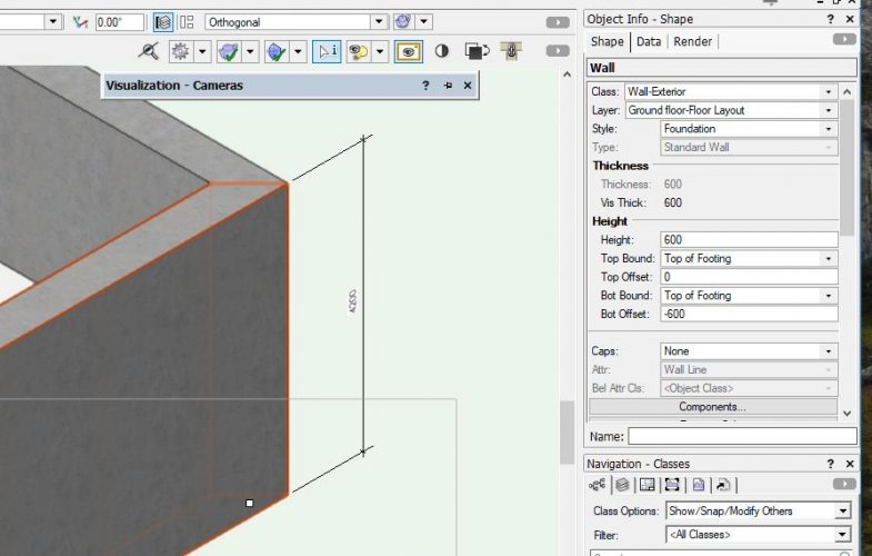
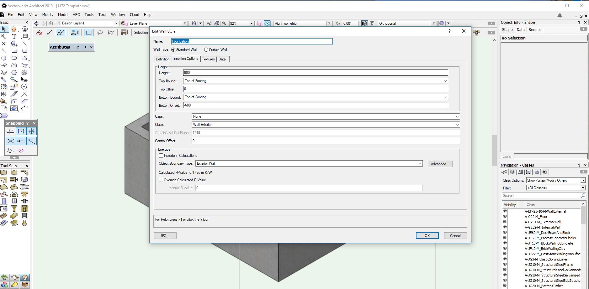
I have worked out that although the wall insertion options were set to the story levels, the component was still on layer elevation/layer wall height, so in this instance I have sorted the problem.. however it does beg the question 'What settings take preference?' as there seems to be little point setting the wall insertion options if they are immediately overridden by the component. It would still be good to have an 'unbound' wall, where the height, top level and bottom level are just set from the OIP. I'm sure I have done this in the past but doesn't work with this file/wall types.... I'm sure it's user error but very frustrating
-
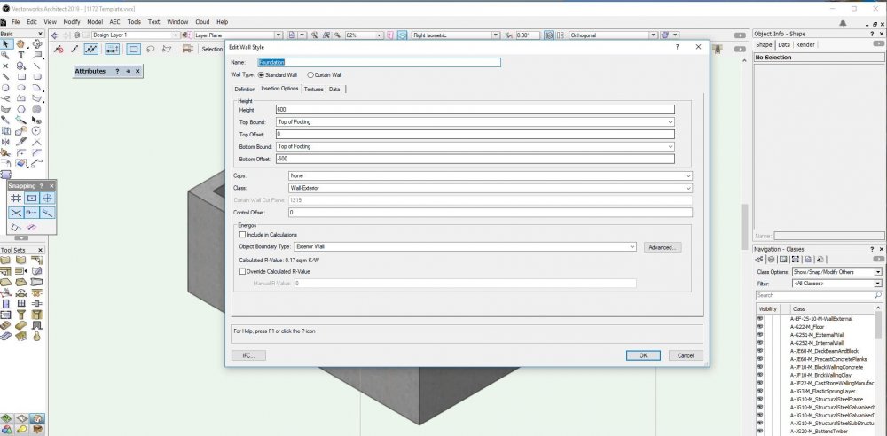
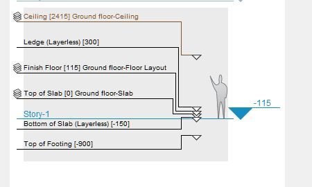
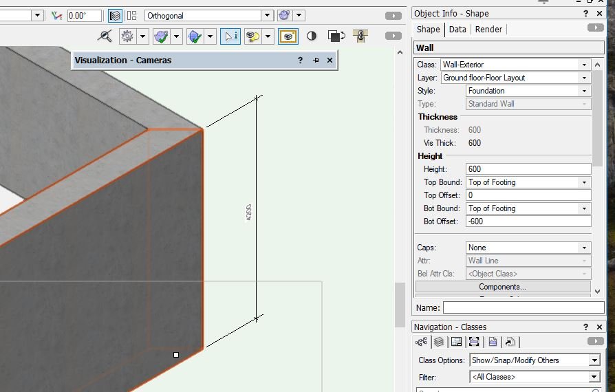
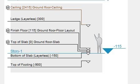
I'm really struggling with walls tying themselves to design levels and the associated wall heights when in some cases I don't want the wall to do this.... Is there a way a wall can be 'unbound'? In the insertion options of the wall type it seems to have to be either layer elevation or layer wall height (for top bounding only), unless I go down the story route. And even then, the top bound seems to still be story height rather than 'top of footing'' as I have set it to. I have read the 'Model set up' tutorial and seen the 'walls and level types' webinar but still don't find it easy or intuitive...Any pointers to the particular issue or a good beginner guide would be appreciated..In the instance shown I am trying to get a strip foundation, drawn as a wall, to go from 600mm below the top of footing story level to the top of footing story level but it is just going to the top of the design layer wall height, making it 4200mm high, and it can't be overridden in the object info pallette..
-
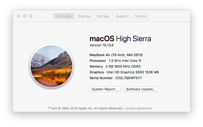
Have tried updating to the latest SP but it fails at the last minute.... Anyone else having a problem or is my ageing MacBook not up to the latest version....?
"Removing Screenshot with serial#" Juan P.
-
Thats great, many thanks
-
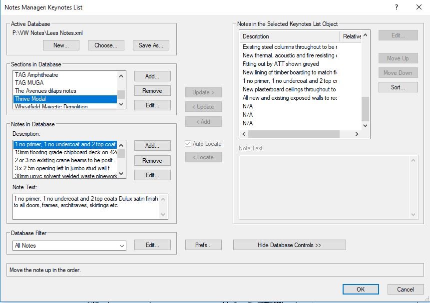
If I have a keynote which I later don't need to use, in the legend it appears as 'N/A'. I can send this to the bottom of the list, but the only way I have found to remove it is to use the 'sort' button, which then re-orders the full list which loses any logic of numbering items consecutively in the viewport. Is there a way around this?
thanks in advance

-
Can the Batt Insulation tool be improved so the ends can be tapered to suit roof detailing, see drawing.
-
3
-
-
Cheers Wes... It might go on the wishlist for upgrades...
-
Is there a way of tapering the ends of the insulation, to better represent the junction between horizontal and raking insulation in a roof ?
Cheers
-
Thanks. Makes sense now....
-
1
-
-
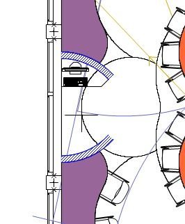
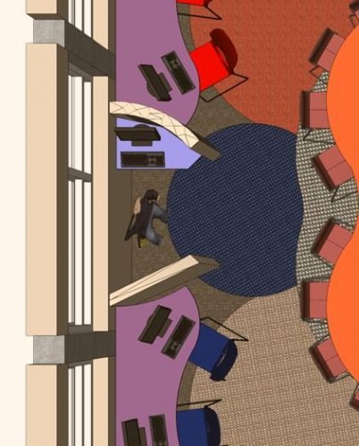
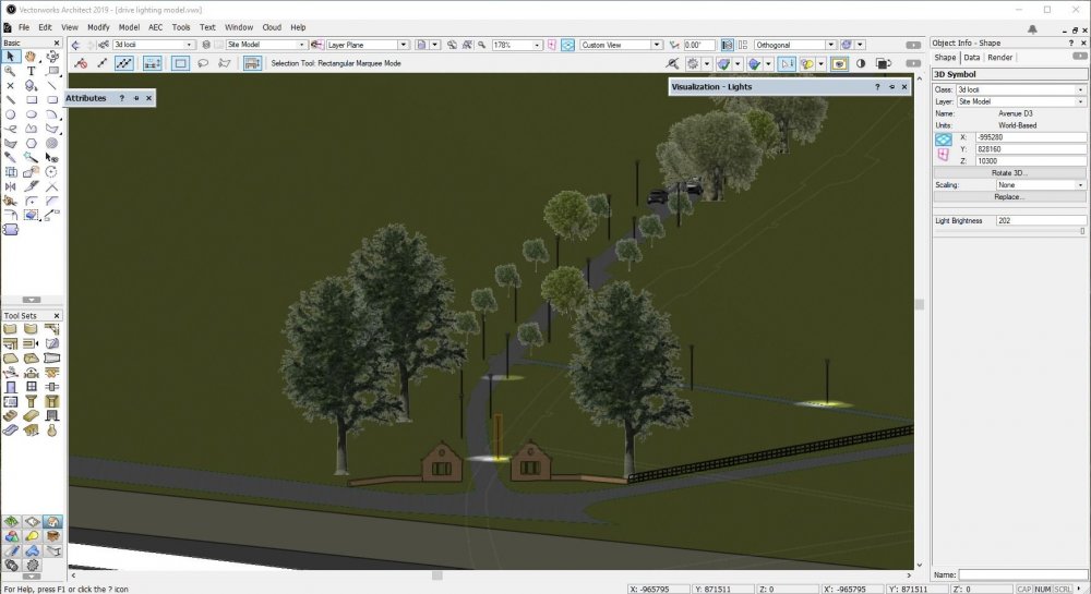
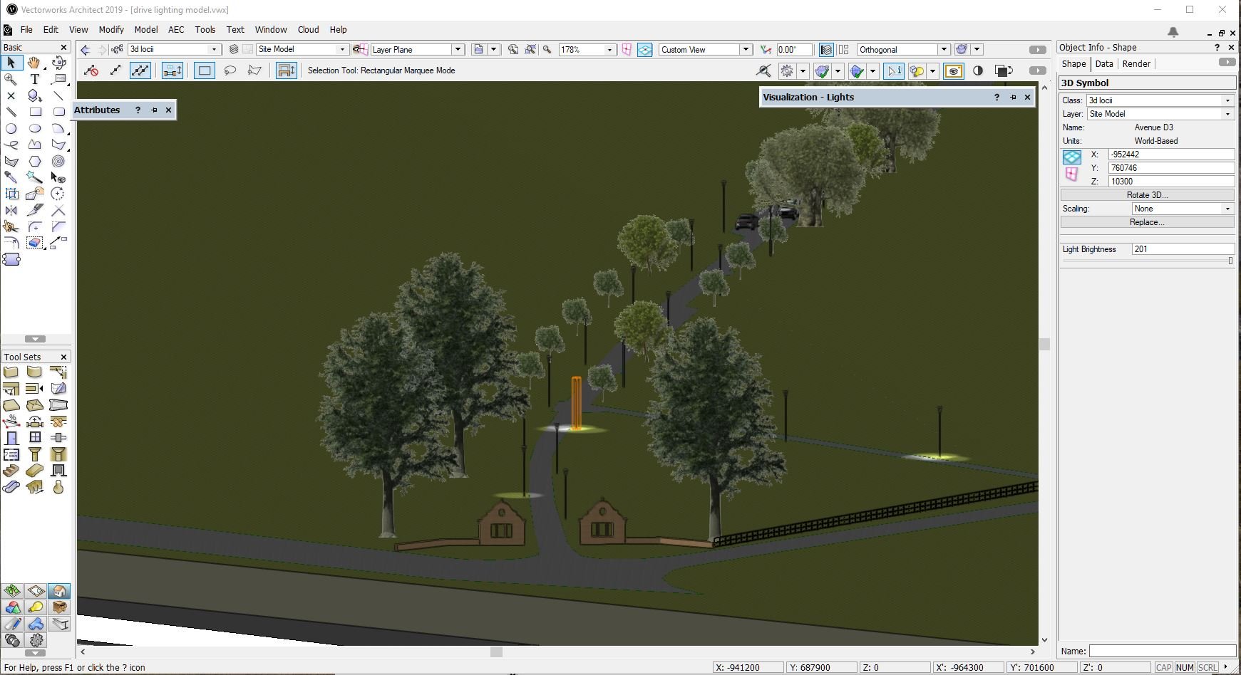
I have created an site model of a long driveway with lighting columns as symbols spaced along it, but when I view in open GL, only 2 of the lights are fully on 'on' at a time, with a third showing reduced lighting... All of the symbols are the same and the light objects within are switched on. To Make a different light 'come on' I have to increase the brightness slightly, but then another light goes off somewhere else.... I enclose a couple of screenshots to demonstrate. There is also a heliodon object but this is turned down so you can see the layout and the light spread better.
Is this a setting or a limitation of my graphics? Thanks in advance.


.png.086ad41a789d0c7db745f3ad1c2db568.png)
.png.5c9dc73eacedab752d40ccde14706ea3.png)


Extrude along path
in Wishlist - Feature and Content Requests
Posted
Frank, Thanks but I appreciate you can move it once in position but I want to know if you can set the origin first... I am adding skirtings and there are lots of sections and I have to reposition each one individually after its been inserted, when if I could set the origin in the profile then copy it, it would save a lot of operations...