


Kevin Allen
-
Posts
2,014 -
Joined
Content Type
Profiles
Forums
Events
Articles
Marionette
Store
Posts posted by Kevin Allen
-
-
It's not a Field, it's a button. It's imperfect, but it is there, near he bottom of the OIPIn 2020, and as I recall in 2019, there is an Add Leader button at the bottom of the OIP.
-
It's not a Field, it's a button. It's imperfect, but it is there, near he bottom of the OIPIn 2020, and as I recall in 2019, there is an Add Leader button at the bottom of the OIP.
-
I think that's in the OIP when. callout object is selected.
-
Me too. I think Ia also sked for this years back as well. I generally use the edit symbol functionality to detail parts of a design, or I have to have a design layer. Being able to create a SLVP from the edit symbol window would clean up my files.
-
 1
1
-
-
I would really try the camera match feature.
-
2
-
-
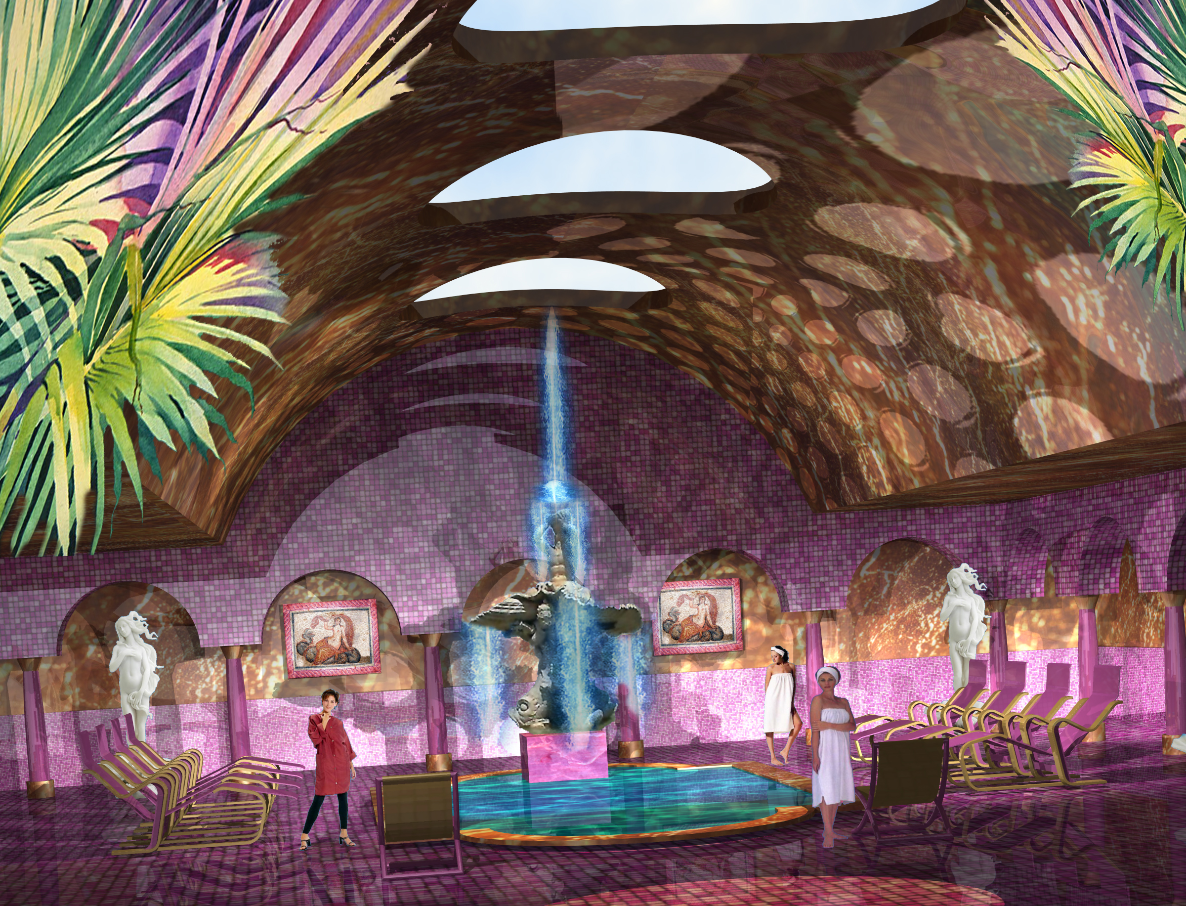
Looks, to me, like you would need to model the floor and the ceiling grid, and use a black background, Keep the light restricted tot he area of the stand.
-
I think I've had the same issue. I generally use simple procedural textures. I recall trying to get a wood grain. but I could not control the direction, so I modified the design.
-
if you convert, keep a copy of the subdivision for future edits. I'm not an engineer, but I can see how mapping directions on faces could be an issue.
-
I have to check, but this seems odd.It might require using the split tool and multiple textures.
-
hmmm, I can't seem to convert to Generic Solid either using v2020. I can convert to a mesh, but that should only provide a shell. Looking at the 'floors' above, I would think that getting the solid from the subdivision would be the first step. Then modeling the outside of the walls and floors as an overall 3D object using simple extrudes and Add Solids would give you something to Subtract from the generic Solid and then the interior detailing could be modeled. I would doo all of this on different design layers to keep everything lined up and to meep the individual objects easier to see as you work.
That said, the failure of the convert to generic solid seems to be a bug.
I don't think either NURBS or using Multiple extrudes will give you what you want. That said, perhaps, and maybe w=using a simply exterment, model the interior hollow, then subtract that from the 'cardboard' overall shape (having assembled that using add solids to make one object), then Co avert the result to a subdivision and while not touching the interior, work on the exterior surface?
-
You should be able to post here or send a forum message or email klad@klad.com
-
can I see the file?
-
It really is best practice in Vectorworks to draw in scale not in 1:1 for large objects.
In terms of the hollowing out. You can convert the Subdivision object to a generic solid, duplicate and scale down the solid and then Model>Subtract to give you 'walls.' However when you do that conversion you can no longer model the object.
I'm thinking there is also a way to do this and keep the object as a subdivision, although that's more difficult and would require some thought. Using the ethos above, the walls would be very regular, keeping it as a subdivision, would allow for irregular modeling.
-
Hmmm, kind of a PITA, but you could do the detail in a separate document and reimport back. Possibly as a DLVP.
-
I do go back to the texture. I wouldn't try to model every last bit of geometry, let a bump map really help you.
-
1
-
-
I might start with something like this, les complex, convert to subdivision and model further.
-
Have you tried subdivision?
-
Not seeing what you’ve done or what you want, I think the answer is less in the model than in the texture. I would use the noise option in the bump shader.
-
yup, I'll bet that geometry is overlapping in 3D space.
-
3
-
-
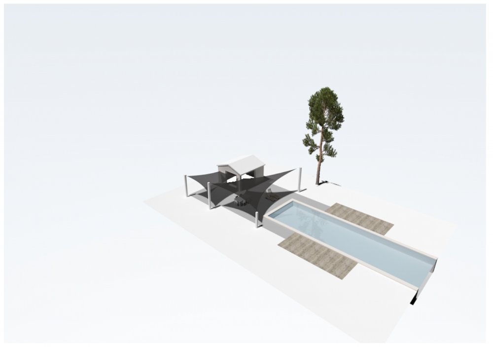
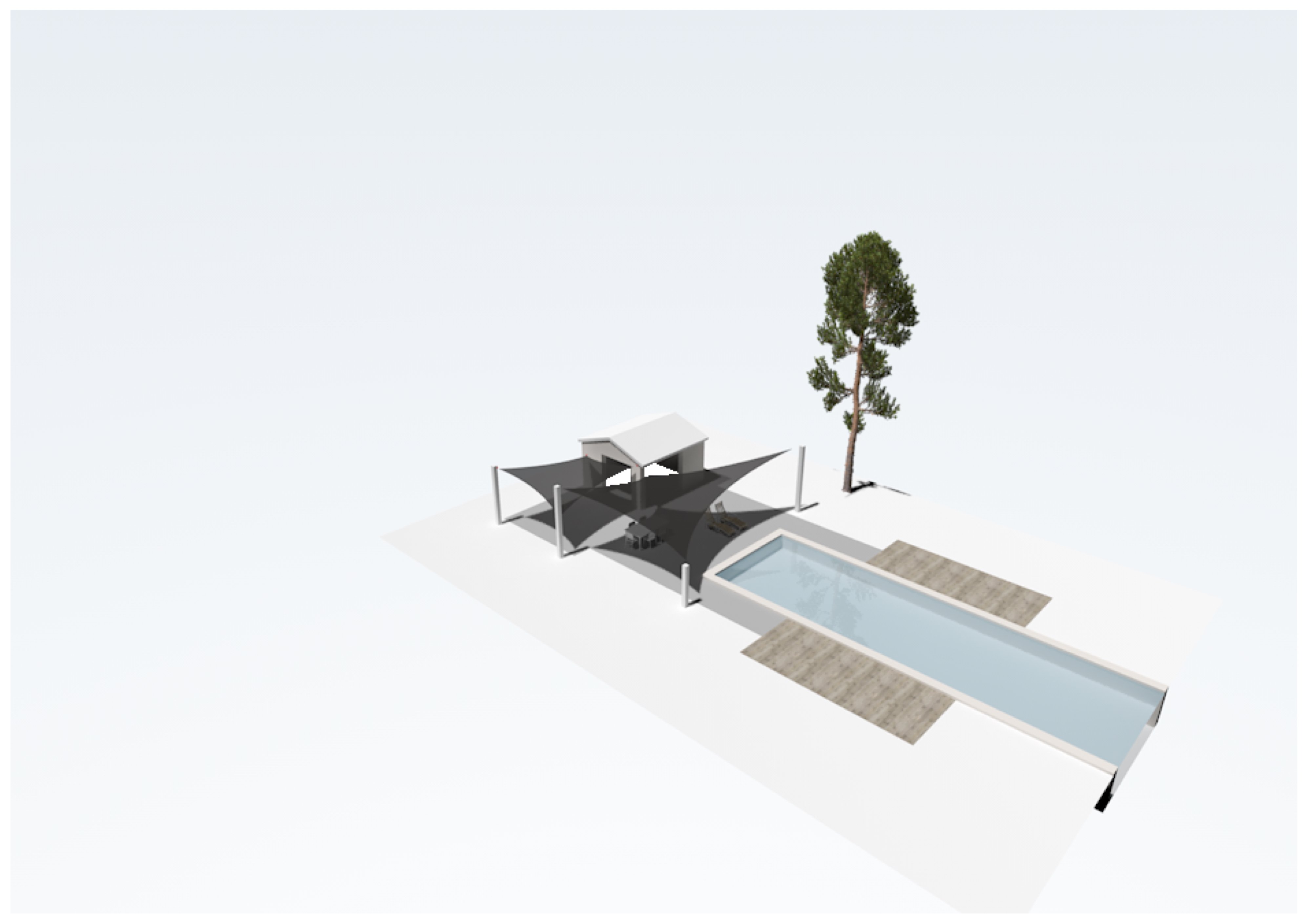
When I render and export from the design layer, I see the issue. When I put the camera view on a Sheet Layer as a SLVP, render and export, the tree is there. Although I think it should work from the design layer, I also think there are known issues with rendering on design layer and using SLs is considered best practice.
-
This is renderowrks and not OpenGL?
-
Can I see the file?
-
I'm not sure I completely understand, but...
1. With a rendered SLVP selected, the Image Effects button should be active in the OIP. however, I don't think when you go back it shows the adjustments, just that you can further adjust. That would be a VE, if I have this all correct.
2. Hatches do not render in Renderworks, BUT you can assign a texture AND a Hatch. So, if you have Knotty Pine wall paneling you can create a texture for modeling, and then assign a hatch in the Texture Definition, with vertical lines for hidden line renders.
-
1
-
-
I'm not sure how this works in the version included with VWX, but in the commercial version manual there are instructions for adding resources. As I recalll, you might open the default content, pick an object, duplicate and modify for the quickest results.
-
1
-
Callout Tool - Leader line points
in General Discussion
Posted
I do not think additional point is possible as you describe.