


domer1322
-
Posts
584 -
Joined
-
Last visited
Content Type
Profiles
Forums
Events
Articles
Marionette
Store
Posts posted by domer1322
-
-
I ask for help ..... I have a styled wall using stories, and I extended the wall using "fit walls to objects" to match the roof. The outer component (blue siding) extended as expected to the roof, but the other components (sheathing, core, gyp bd) did not. I checked the settings in the wall style components, and they all seem to be the same. Can anyone show me what I'm doing wrong ? Also ... is it possible to adjust the height of the components of a wall by clicking and draging on the wall vertex in edit mode ? (I can't figure it out.)

-
Dinosaur question ....
I may try to update my current iMac OS Yosemite (10.10) without updated VW. I have VW 2015 and I found two different sources of compatibility information for VW. One source says VW 2015 can run up to Mac OS El Capitan (10.11) and the other says it can run up to Sierra (10.12). Can someone (who knows) confirm which source is correct ? I attached screen shots of both sources, and they both seem to come from Nemetschek 'official' sources.
Also: i found a thread on this forum that detailed lots of issues with OS El Capitan when it first came out, but it also seems to indicate updates to both OS 10.11 and to VW 2015 fixed the issues. Can anyone confirm if these things work well together ?
VW compatibility with Mac OS.tiff VW compatibility w Mac OS.tiff
-
Art V: I'll check out the other file formats in the future. Right now, I ended up downloading dwg files in elevation and found it was fairly easy to trace them and build my own appliances. Interestingly, when I went back to the website to download some more files, I found that many appliance models have a link to download files, but they don't tell you which file format. From experience. it seems they are mostly dwg. Oddly, I also discovered that GE website has downloaded files for some of their products, but not all. For several refrigerators, I clicked on "download CAD files" and get a blank screen. I guess it is random. Here is the weblink: https://www.geappliances.com/appliance/GE-Profile-27-9-Cu-Ft-Smart-Fingerprint-Resistant-4-Door-French-Door-Refrigerator-with-Door-In-Door-PVD28BYNFS
-
thanks for the reply ... you confirmed what I had expected to be true .... there is still no good way to import these 'non-vectorworks' files. I trace them occasionally, but was hoping there was a better way. As for upgrading VW .... I'm retired, so using VW is not much more than a hobby. I'm trying to see how long I can keep my current iMac that works with VW 2015 quite well. Since I have to keep the current Mac OS (10.10.1) to operate with VW, I can't upgrade the internet browsers, so eventually I'll have a "non-internet" computer and I'll have to figure out if an upgraded VW is worth it.
again .. thanks.
-
I'm sure someone has figured this out (but not me). How can I import a 3D symbol like a microwave from the General Electric website ? When I import the dwg 3D block, it comes out to be a mesh that can be broken into 3D polygons, but I can't figure out how to transform all the thousands of 3D polygons into an object that VW uses like extrudes, Generic solid, or other simple forms. I want to do this so that I can apply the correct textures. I attached an example import, as well as a screen shot showing the many many many polygons that make up the object. I've fiddled with all the dwg import controls, to no avail. (I'm using VW 2015, ..... so therefore I wonder .... is this still a problem with VW2020 ? )
Alternatively ... does anyone know a good site for obtaining VW models of appliances, furniture, etc ... ? (Desire manufacturer exact models.)
-
is it possible to use the VW wall styles to represent a wall that has different materials on the lower portion of the wall than on the upper portion ? That is ... what if my wall has a CMU veneer on the bottom 3 feet, and then uses regular clay masonry for a veneer above the CMU. It seems to me that the VW wall components are not allowed to "stack" on top of each other and must be in different vertical planes. I attached a sketch of a vertical section.
If it is possible, please tell me how. I know I can draw 2 separate walls for the veneers, but this very cumbersome, especially when trying to insert a window or door.
My goal is simply to be able to represent the wall correctly in both 2D and 3D views. I'm not concerned about the proper height for the cut plane for a floor plan.

-
jblock .... I sent you a message and repeat the main part here ...... I was very surprised to find from another test that VW2015 now DOES ACTIVATE on my old laptop using Mac OS 10.10.5. If anyone reading this cares, I now retract my earlier disparaging post about the lifetime of VW products. I don't know what happened, but for a couple years it definitely did not activate, and I now have no idea why it activates now .... but I'm happy.
-
 2
2
-
-
I forgot to mention one other important factor why you can't keep using VW forever .... I try to use VW 2015 on my old Macbook Air, which also can not update to the newest OS nor browser. Since VW requires internet verification, when I start VW2015 it will not verify on the internet. The VW tech guys confirmed with me that the internet verification for VW2015 will not work, and thus, it will not start up. They have no intention of fixing it. I suspect this will happen to all subsequent versions of VW. Also ... there is no setting for which browser the internet verification uses, so I can't try to use a more recent Firefox browser. (setting the default browser differently makes no difference)
-
TomKen ... I just had to put my two cents in about one comment you made. I am retired and kept VW to do (mostly) charity work. I thought I could just keep it "forever" since it was not on subscription. This is proving to be a mirage. What happens is that I am now unable to upgrade my Mac OS because VW 2015 won't work on a more recent Mac OS. Since I can't upgrade my Mac OS, I can not upgrade my Safari browser. I'm pretty well constrained to use Firefox since some websites (like my bank) don't work with an old Safari browser. I figure the age of the OS and browsers will become intolerable within 2-3 years. Thus, my conclusion is that keeping the old VW running won't work anyone more after about 8 years. At that time I'll have to decide to buy a whole new computer system and VW, or give up on CAD work. (My other computer, a 16 year old iMac, still works really well as a music player and to show photos of project sites while I'm drafting on my late 2012 iMac.) This sort of constant-update cycle is exactly what everyone has complained about since Steve Jobs was working in his garage. No solution in sight.
-
thanks, but .... can someone confirm that the Attributes Mapping tool will allow changes to the mapping of an individual wall component ? I've been trying repeatedly to make it work, but it only works (for me) on unstyled walls when they are rendered "by object" and they don't have components.
-
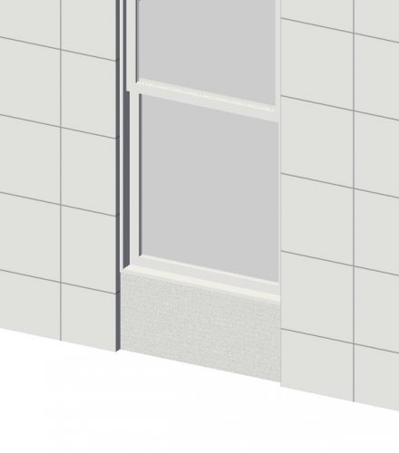
This ought to be simple for anyone who knows what they're doing ..... in the attached image, how do I move the lines in the wall surface such that one horizontal line is aligned with the sill ? (right now it is about 4" lower than the sill) I tried using the attribute mapping tool to no avail. I suspect there must be something I don't know about the AM tool. I thought of the setting for textures that assigns a global 'Z' value, but it is grayed out on the OIP. The wall in the image is a styled wall with an outer component of plaster and I only want to move the texture on the outer component without moving the texture of the other components (although ... I can work around it if I must ... please tell me how to move the texture) I even tried reading the manual .... which doesn't seem to address how to move a texture on a wall.
Thanks for any help .... (sorry, but I'm using VWA2015, so please consider if your advice is OK for this older version).
-
is it possible to develop a worksheet that lists objects based on the object size ? I tried setting the criteria in the data base line. First I set the criteria based on the class. But for the next criteria there are hundreds of possible fields, but none of them say "length" "height""depth" unless it is associated with a PIO like a window. In my case, I often design simple ADA ramps for charity, and I'd like to automatically do a material list when I get done. For example, I might have joists that are extrudes, or generic solids, or a solid subtraction, and I'd like to lump them together based on size, so I know that I have to order 16 ft long boards or 8 ft long boards, etc.
Any help with a proper formula/criteria is appreciated.....
-
1
-
-
I have an old file (a 3D model of my own house) that I've been updating or changing for years. I notice that my door plug-in objects do not allow me to assign door hardware to them. That is, I click "settings" on the OIP then in the door dialog box I pick 'hardware' and the area where there is normally a list of all the available hardware sets shows an empty box. When I click on the box "include hardware" it makes no difference. I have some hardware sets already in the resource browser of this file. I tried to "update plug-ins" as well as "reset plug-ins" but it made no difference. I do not have this issue with other files.
It seems to me I have to tell VW that there is a hardware file in the 'libraries' folder, but I can't figure out how do that.
Help .... please .... (I'm using VW 2015 but I hope you'll consider replying even if I'm using old software).
-
Boh: thanks for the reply. I needed someone with real skill to verify that it isn't possible. I suppose sometimes the 99% technique might be OK, but I want to render it in OpenGL without seeing the line. Also, in RW the shingles don't line up. I found a not-too-complicated work around .
It is a bit frustrating though ..... this roof shape is very common in my area for old ranch houses that are now being renovated. The roof tool let me down.
-
1
-
-
you could try this work-around: make the walking surface of your ramp as a slab or generic solid. Then use the extract tool to extract the edge of the slab as a NURBs curve. Use the NURBS curve as the path for an extrude along path with the handrail profile. Also use the NURBS curve to duplicate many balusters along a path.
This will work if the railing and guards are not too complicated, but even small ironwork patterns can be duplicated along the NURBS path if you wish.
I was doing this for a project when I read your inquiry and it is working for me. I hope this helps.
-
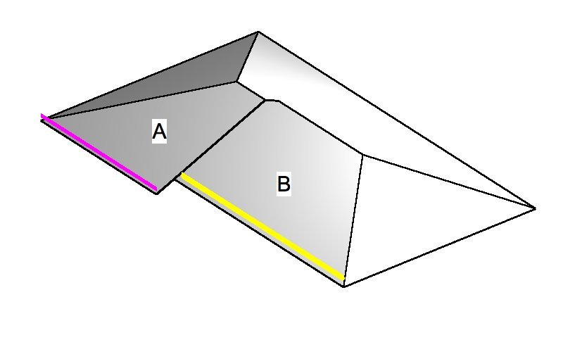
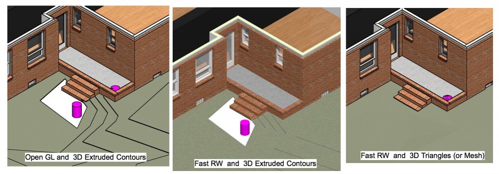
It seems I can't reproduce this very common roof structure and ask for your help. In the attached image, I want to make the plane of roof A be co-planar with roof surface B, as well as have that roof portion overhang a bit as shown. I understand it means that the bearing height of the wall shown with the purple line must be lower than the bearing height of the wall with the yellow line. However, when I try to reduce the bearing height of the purple wall, it will not allow me to fully lower it so that the planes are co-planar. It does allow me to lower the plane of roof A, but not enough to make it co-planar before I get an error message.
I know that I can change the roof into generic solids and then make the change, but I don't want to do that, since I can't return it to being a roof object.
Any help is appreciated ..... thanks
-
Ok .. thanks .... I'm just repeating the answer here so that I can find this thread in the future ... in case I forget again. The answer was to set the jamb to a class, and then hide that class.
-
1
-
-
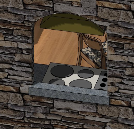
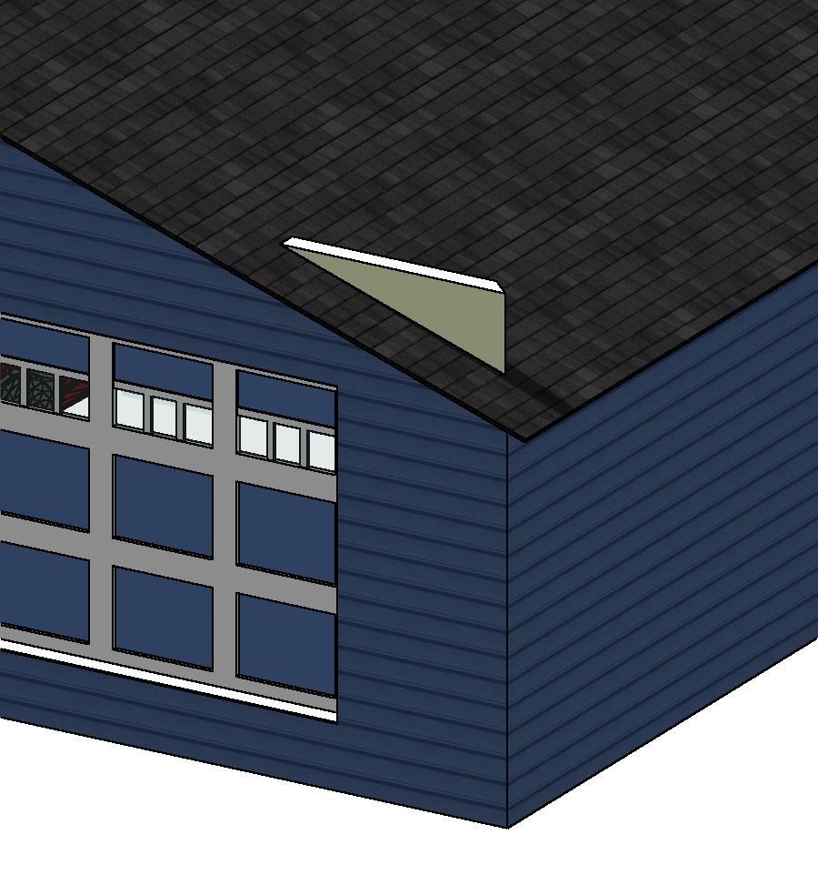
At one time I knew what caused white lines to appear around openings when inserted into a wall, but now I forgot and I can't fix this. I ask for help ... look at the attached image and tell me how to get rid of the white lines that appear around the opening on the corner edges of the opening/wall. It occurs in OpenGL and RW.
-
UPDATE: I discovered that I can insert a window dormer from the VW libraries ... IF.... I click and drag it directly on to the roof. Whenever I first drag it on the drawing (but not on the roof) and then I drag it over the roof (in top/plan view) then it does not insert itself as a dormer. This seems odd to me. Is it supposed to work that way ?
-
thanks ... but I tried that multiple times. Perhaps I should have asked the question this way .... When I drag my window symbol over the top of my roof, and the roof does not high-lite nor show any indication that it will insert it, then what have I done wrong ?
-
I'm embarrassed to ask this .... I want to make a roof dormer and the manual says to insert a window symbol, but NOT a plug-in object. I can't use the 'window' tool because that makes PIOs. Then I went to the libraries, and every library has a PIO for windows from various manufacturers. So ... how do I convert a Plug in object to a symbol so it can be inserted in a roof to make a dormer ? I tried to 'ungroup' it but that won't let it be inserted.
-
well ... thanks for the effort. I've been trying to figure it out, and this is my observation. The DTM model is set up by using perimeter 3D loci in the source data, all set to a certain elevation (let's say -2 ft) I'm not using imported survey data. These elevations are noted by me in the field without a survey. The 'hole' seems to be caused by two 3D loci that have an elevation lower than the perimeter loci (= -2 ft 3 inches). So, I guess I solved this by changing the perimeter boundary loci to be lower (- 3ft). But this puzzles me because I had my DTM settings set to minimum elevation much lower ( - 5 ft) so I should have been able to see everything without a 'hole' down to minus 4 ft --- right ?
Perhaps ... is it possible that VW won't process negative elevations correctly ? In this case, I set up the finish floor to be = 0 for my convenience.
PS: I've tried to find corrupted source data based on your comments, to no avail. I've had multiple freezes with this file whenever trying to render using 3D extruded contours, but can't figure out why. (It doesn't happen every time ... the worse kind of issue to solve.)
-
yes ... thanks for your reply .... I stripped down the original file and attached it. I've found that I can move the "hole", but can't get rid of it if I try to keep the same elevations. I attached a jpg image of the same 'hole' ... after I moved it. I know that i can eliminate it if I change the elevations in the DTM source data, but I don't want to change those as I'm trying to model actual conditions. NOTE: I am working in VW 2015.
-
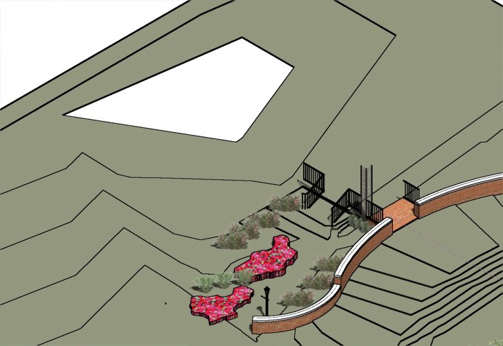
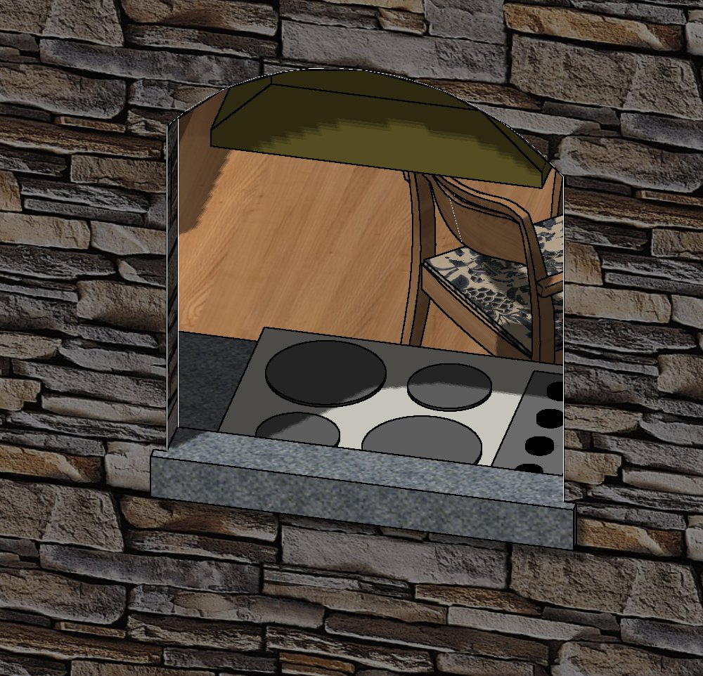
Can anyone explain what is wrong here ? The attached image shows an existing topographic DTM that has a depression next to the steps. When setting the DTM to show 3D extruded contours, there appears to be a hole in the DTM (next to the purple cylinder). Rendering with OpenGL or RW has the same result. However, the 3rd image shows the DTM with 3D Mesh or 3D triangles instead of extruded contours. I tried to reset the DTM settings to have a lower minimum elevation, but it didn't fit it. All images show only the existing DTM (not proposed) and the proposed layers are turned off. Any suggestions ?


wall height help
in Architecture
Posted
OOPS .... never mind. I discovered my checking of the component settings wasn't too good. I was puzzled for 30 minutes, then posted. Of course, as soon as I posted and returned to the issue I discovered the faulty settings. However, I still wonder if it is possible to change the component heights by clicking and dragging. Any thoughts?