


Mitchell (the other one)
-
Posts
87 -
Joined
-
Last visited
Content Type
Profiles
Forums
Events
Articles
Marionette
Store
Posts posted by Mitchell (the other one)
-
-
Just wondering how everyone is creating and placing doors. Previously I had a master file of doors and would just copy and insert the first instance as needed in my drawing. After that using the Eye Dropper tool in the Symbol Insertion Tool I would place further instances of doors as needed. Then I started exploring Door Styles and liked the greater degree of control but wondering if all doors in a drawing should remain as PIOs or are others creating a symbol for each door size / type once the PIO is configured as needed. I like the Use Wall Depth for the jambs but once a PIO has been converted to a symbol the jamb depth doesn't seem to adjust.
-
Thank you - I was thinking along similar lines but late in the evening it just wasn't working for me.
"As a test I just grouped the Top view objects and then used the OIP to set the center of the group to 0,0. "
Could you walk me through the steps in using the OIP to set the centre - I haven't used this technique before.
-
Certainly, simple file attached.
-
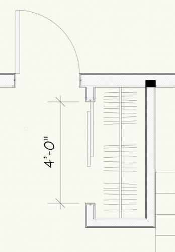
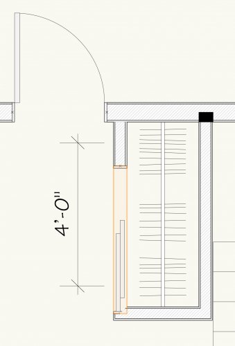
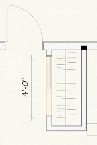
Haven't had this issue before. Creating some new door symbols with door styles. Flipping this bypass door:
- Flip 1 - works correctly, door leafs flip side to side,
- Flip 2 - door symbol goes end to end but the door shifts down,
- Flip 3 - works correctly, door leafs flip side to side,
- Flip 4 - door symbol goes end to end but the door shifts up and does not return to the original position.
I've looked at the symbol to see if there is a piece off to one end but didn't see anything.
Any suggestions?
-
1 hour ago, TomWhiteLight said:
Hi Jim I can send you a file with some great renders. I will email you a link.
Could I take advantage of your offer as well? I'm just learning some RW techniques and I'd like to see where the bar is set. Thanks.
-
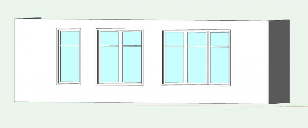
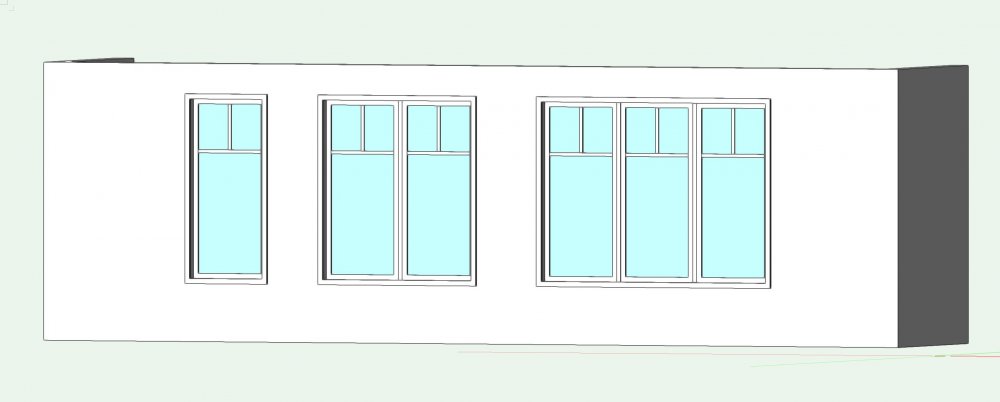
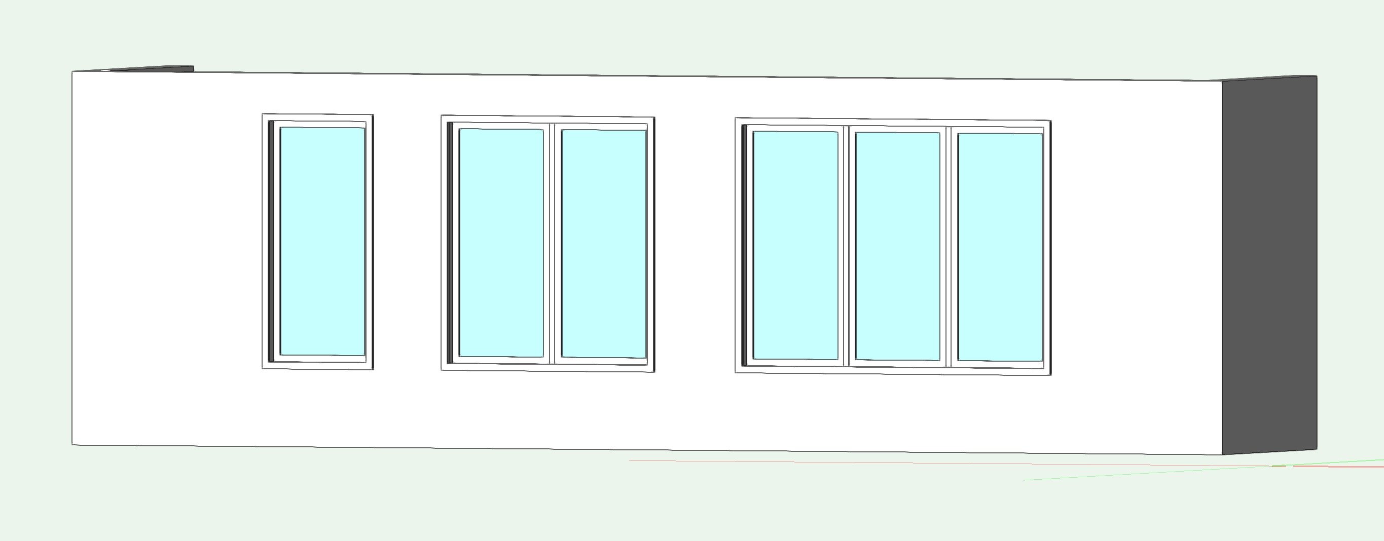
The attached elevation has background rendering set to Artistic Renderworks (Lines and Shadows, Edge at 0.5, Colours to black and grey), foreground rendering set to Hidden Line (Angle 1, Generate intersecting lines, Display surface hatches, Display text and markers). Any input on where the extra lines running to the windows are coming from and how to eliminate them?
-
8. If steps 1 through 7 don't work, open your recent backup copies and see if you can go back to a point where your drawing was as expected.
-
On 4/3/2020 at 8:24 AM, Wes Gardner said:
@aduncan2, for lines, use the Connect/Combine tool - see attached video...
Well, that 17 second video has given me a new tool / technique - thank you.
-
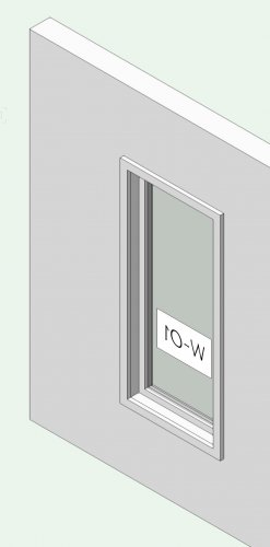
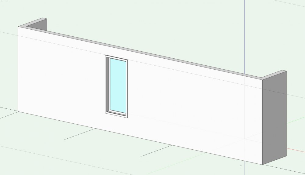
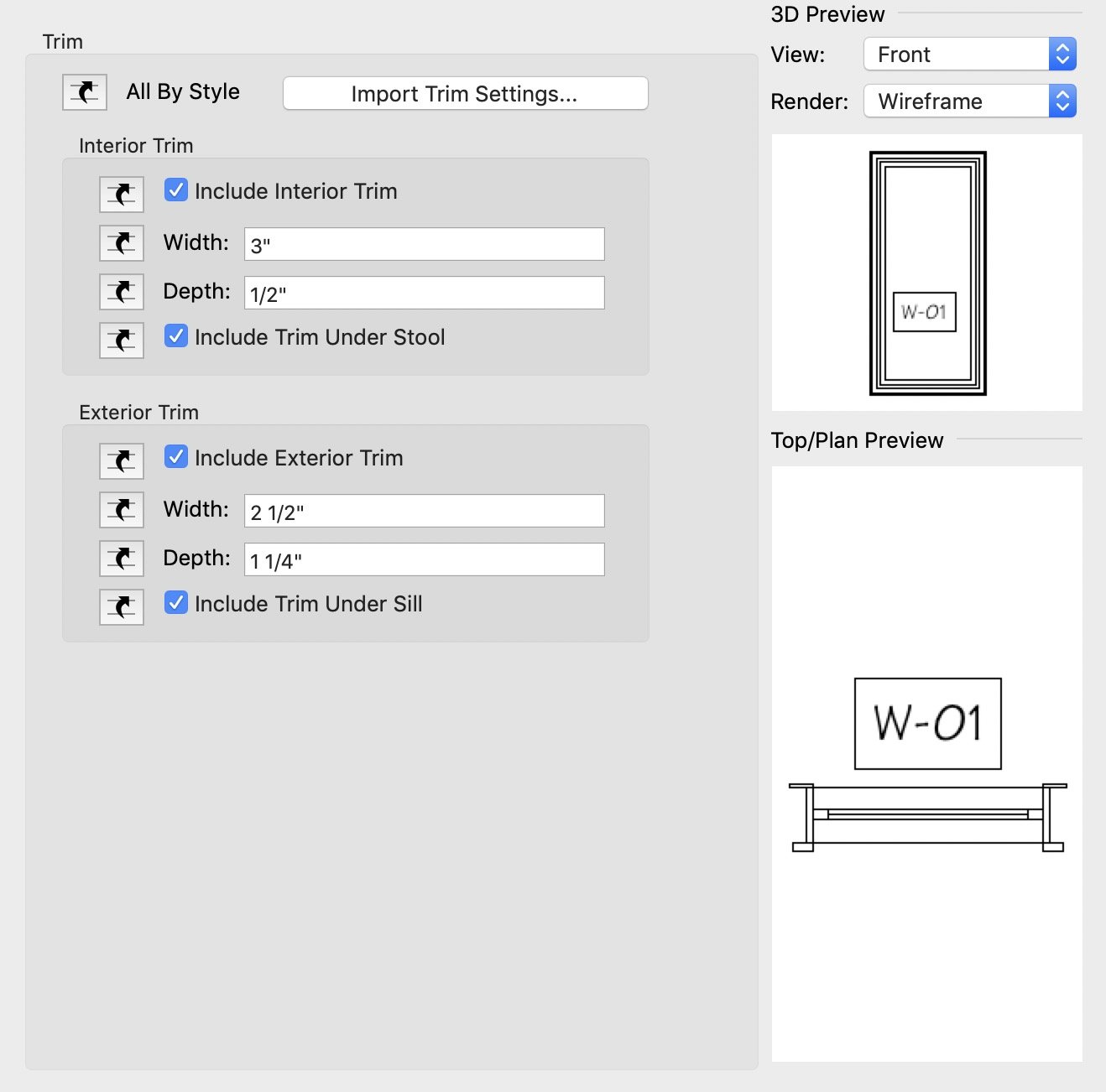
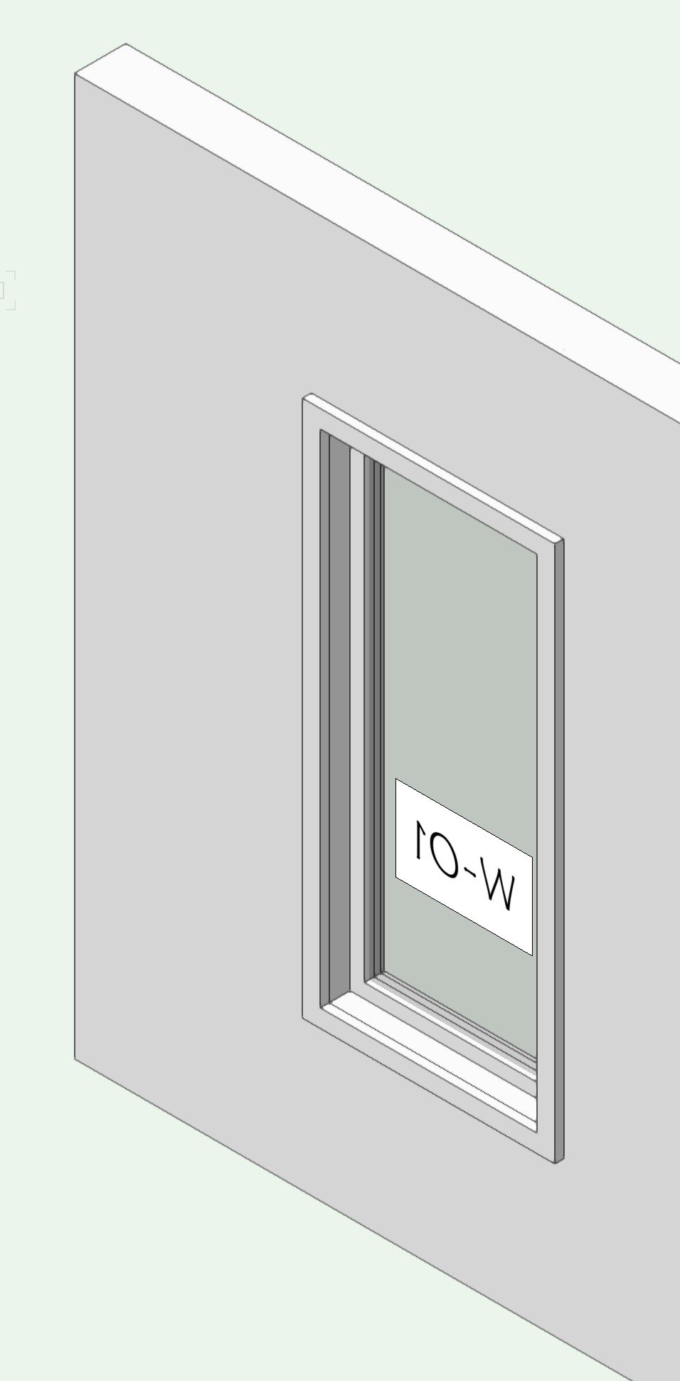
More window tinkering, social distancing lends itself to learning more tool features. The first image shows a window with interior and exterior trims. The second image shows the settings for the sizes of the trims, this means on the first image the interior is at the top, the exterior is at the bottom. Then in right axiomatic view, the tag is shown facing to the interior. Or am I missing how interior / exterior relate to the wall and I have pretty much everything flipped? And if flipped, how do I recognize this while laying out a floor plan?


-
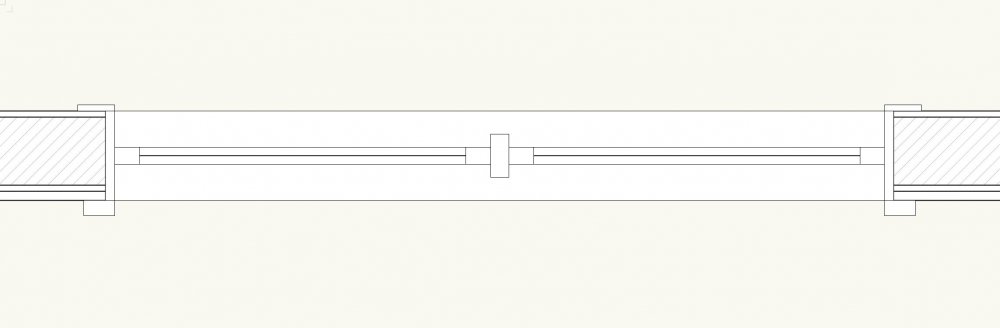
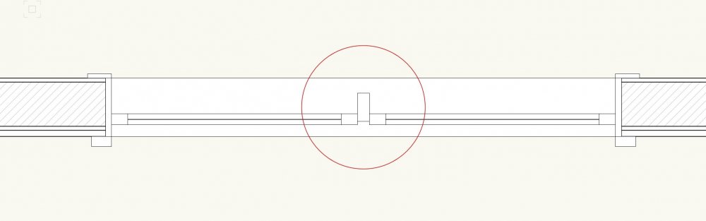
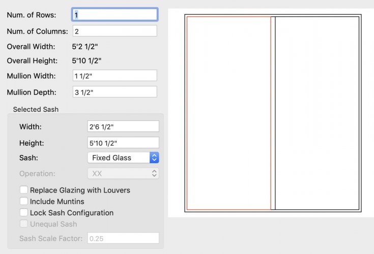
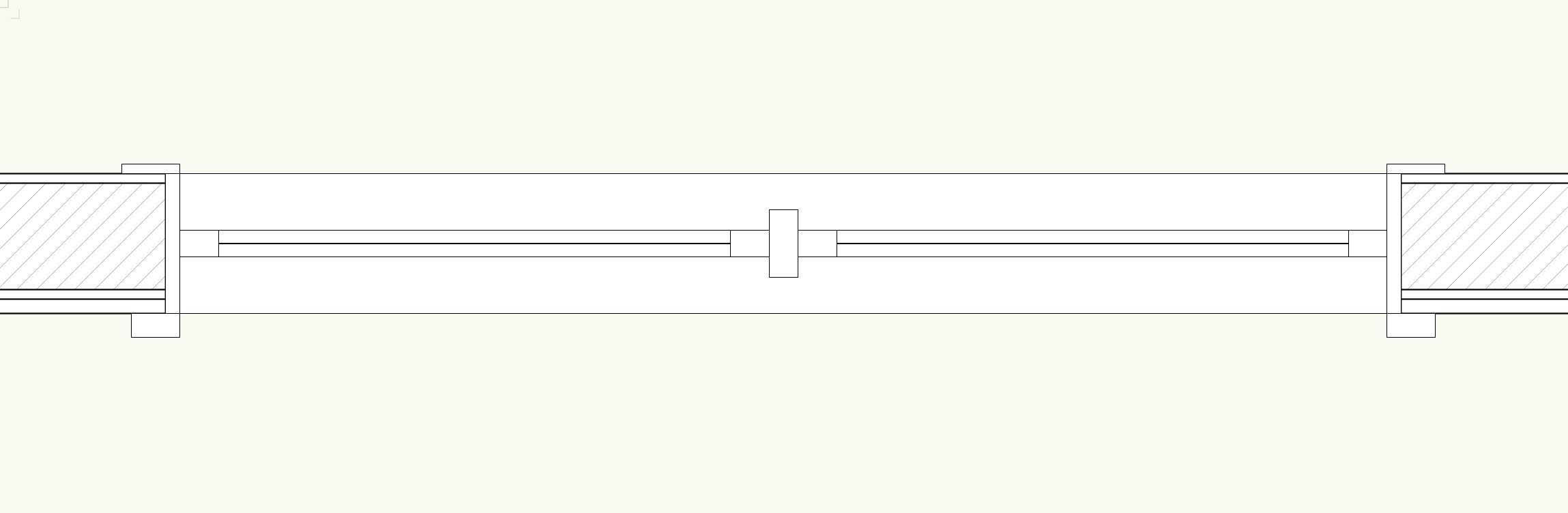
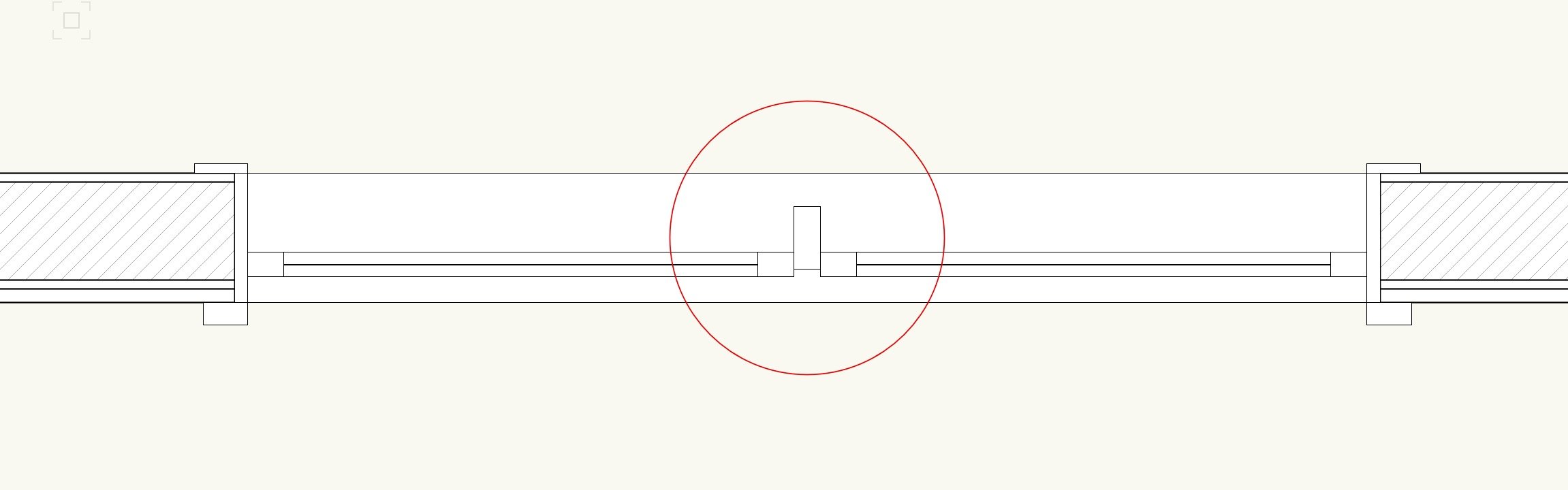
Just tinkering with the window tool and have a question about how the sash and mullion are related. The first image shows a window with a custom sash to represent two window units mulled together. The second image shows the window sash offset to locate it closer to the exterior face. The mullion does not offset with the sash and there doesn't appear to be a setting where one can offset the mullion. Is there a setting I haven't found yet?
-
4 hours ago, michael john williams said:
it would be a great improvement if there was a single central place where all this training was shown.
Have you looked at the Vectorworks University?
-
Over at the Vectorworks University I'm working my way through the 'Model Setup' course to see if I should incorporate Stories into my workflow. Starting the section on Wall and Slab Styles and came to this paragraph. It could be me but I'm not sure how this relates to this particular topic. Was the course designer having a 'moment' or is this an easter egg to see if anyone actually reads the course notes?

-
Don't think this has been posted elsewhere, Vectorworks has made a number of their online seminars free until June 30. I just took the Architect Essentials and the Vectorworks Hidden Treasures seminars and picked up a number of tips that I will explore further. If you have time on your hands at the moment, these are worth looking into. Thanks VW.
-
 1
1
-
-
I do something similar fairly often. I usually duplicate the symbol so the original can remain in place and the duplicate can be adjusted, If you didn't want two symbols for some reason, then place a second symbol and convert to group. Then edit the symbol or group using the reshape tool to move the legs but "stretch" the seating portion.
-
1
-
-
2 hours ago, Andrew Bell said:
Apple and Google have moved their cancelled public events (WWDC and I/O) to online events. Is there any content from the summit that could be moved to online as well? (given that a number of us now find ourselves with unexpected time on our hands)
-
6 minutes ago, Andrew Davies said:
I am trying to brush up with 3D skills and learn some things that have always puzzled me, but I have never had time to investigate (Yes- 50% of my work has been cancelled!)
Not an answer to your question but I am in similar situation and was starting to look for links and YouTube content to brush up my skills.
-
And what about today's headline . . . . .
SACRAMENTO, Calif. (AP) — Gov. Gavin Newsom has issued sweeping, statewide “guidance” in response to the coronavirus pandemic, asking Californians to postpone all non-essential gatherings through the end of March, including even small social gatherings in places where people can't remain at least six feet apart.
-
A little later after some tinkering I solved the wall cutting / gap issue with new 3D loci at the corners of the window frame. (not the trim) And then started again with a different idea. Using two symbols, one for the window and a second symbol for the mullions with class control I get the look and control I was looking for.
-
1
-
-
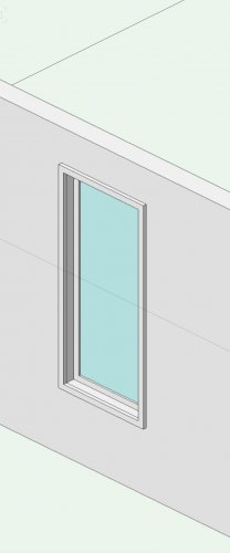
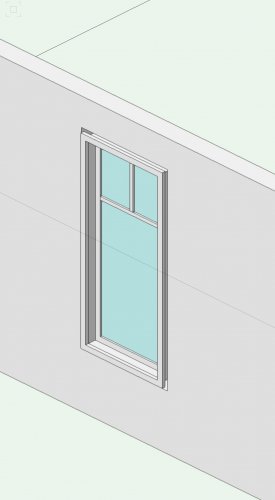
I'm tinkering with a window symbol to add a different munition pattern. The first image is the window inserted in the wall and looking as expected. The second is the same window after I edited the 3D component adding the new muntins. The window symbol now cuts the wall inline with the exterior edge of the interior trim. I tried adding 3D loci and made a further mess of things so thought I'd post the question for guidance from wiser minds. Thank you in advance.
-
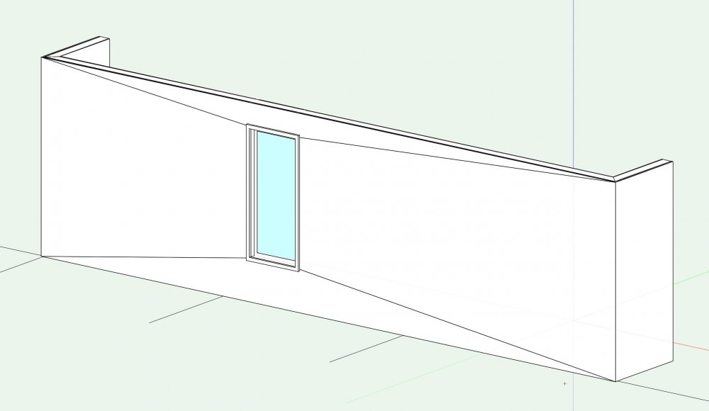
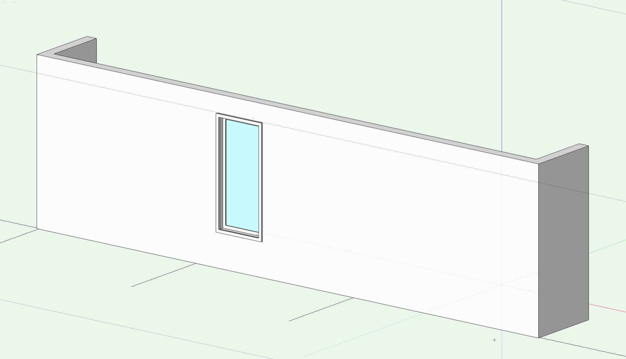
I've attached two images showing my question about an inserted window. The first is rendered in OpenGL - everything looks as expected. The second is the same wall & window rendered as a Unshaded Polygon. The second image seems to show "creases" in the wall running from the wall corners to the corners of the window. Have I set something wrong on the window tool?
-
There are several You Tube videos dealing with classes and layer organization. Once you get a handle on them you will find them a very powerful tool.
-
Can you assign each colour to a class and then switch between classes?
-
42 minutes ago, SeanOSkea said:

Where is that first icon on my toolset? Do I click it and lunch is delivered?
-
1
-
-
I use 2019, but have looked at 2020 and agree. I hope they "address" (read fix) this in 2021 and I'll just avoid using 2020 all together.
-
1
-


Flipping doors
in Architecture
Posted
Ahah, Step 1, if you are not using Rulers, turn them on, then you will be able to see where 0,0 is. Now it makes sense - thank you.