


Hobbsies
-
Posts
36 -
Joined
-
Last visited
Content Type
Profiles
Forums
Events
Articles
Marionette
Store
Posts posted by Hobbsies
-
-
On 1/11/2018 at 5:32 AM, markdd said:
This idea might be a good workaround to get you near to what you are looking for:
You could make special "Instrument Summary" Symbols. The 3D views could be created in a worksheet and then placed as a screenshot into a duplicate of the instrument you want to count in the Instrument Summary Tool. For the Instrument Summary tool to count the summary symbol the Light Info Record Instrument Type needs to be identical to the symbol you are substituting.
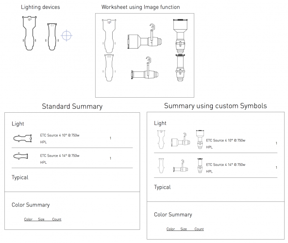
I have done it with a horizontal orientation, but you could arrange the "Summary"symbol any way you like. Take a look at the file which I have attached below.
Hope that helps.
Mark
Wow, I really like this idea! I think you were the one who helped me fix my strip light symbols too.
-
I get the attached error every time I close VW2018. It happens with all files.
Problem signature:
Problem Event Name: APPCRASH
Application Name: Vectorworks2018.exe
Application Version: 23.0.2.0
Application Timestamp: 5a0ccc78
Fault Module Name: Vectorworks2018.exe
Fault Module Version: 23.0.2.0
Fault Module Timestamp: 5a0ccc78
Exception Code: c0000005
Exception Offset: 0000000000c7a131
OS Version: 6.1.7601.2.1.0.256.48
Locale ID: 1033
Additional Information 1: 9667
Additional Information 2: 9667a31dfb9df0d49a160f54902312c8
Additional Information 3: 60a3
Additional Information 4: 60a31a21b2c49acce548aa18c8ffb4f8Read our privacy statement online:
http://go.microsoft.com/fwlink/?linkid=104288&clcid=0x0409If the online privacy statement is not available, please read our privacy statement offline:
C:\Windows\system32\en-US\erofflps.txt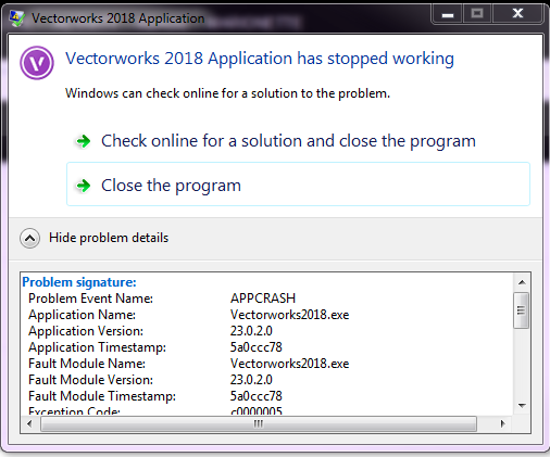
-
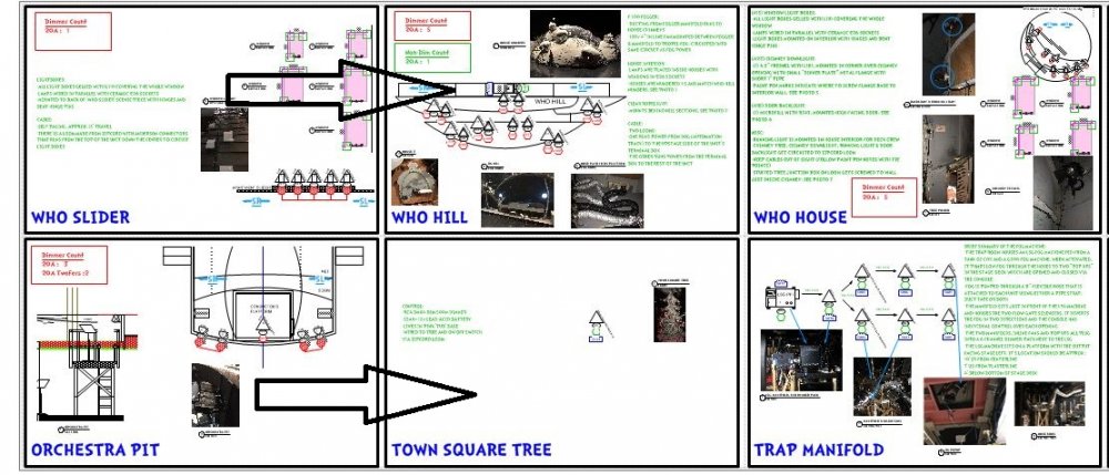
I have several sheets with multiple pages laid out. In most of my sheets, the print order is down, then across. However, I have one sheet that prints across, then down. How do I change that?
See attached photos. arrows indicate print order.

-
On 10/17/2017 at 6:37 PM, markdd said:
Thats it.
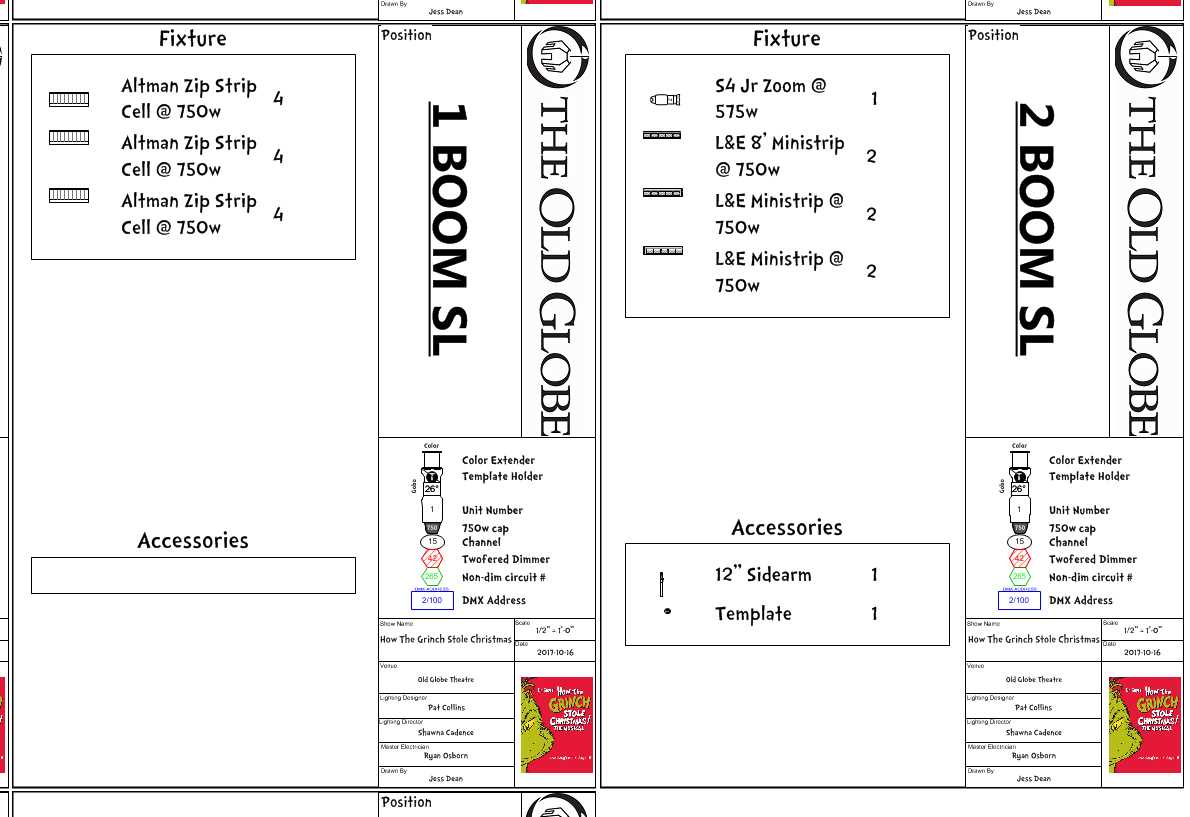
Here is an example. You can create a separate instrument summary symbol if you like. I do mine like this and use these for my instrument summaries. I duplicate one of the nested symbols, strip out the 3D portion and adapt the 2D portion. The Light Info record data stays the same:
The resulting Symbol maintenance window should look like this:
I have attached the file here as well.
Instrument Summary Tool v2016.vwx
Got it working!! Thank you soooo much! <3
-
14 minutes ago, JBenghiat said:
What Mark is saying is that when you have things set up correctly, the combined symbol is unused and the parts show up as used. Indeed this is the case when you look at the actual symbols
in use — you don’t have any Lighting Devices actually utilizing the combined symbol, only separate Lighting Devices for each part.
Counting, on the other hand, looks for unique Instrument type data, not unique symbols. This is by design: you might have multiple symbols representing the same type: over hung / underhung, plan view / front view, etc. I have a version of my source fours that is slightly shorter for pipe ends, etc.
This also works for strip lights, where you count up all the cells, but also divide by the number of cells per unit. You can have whatever symbol you want to represent them in the key. For long PAR 56 strips, I have a symbol with a break line showing only the start of the strip. I would never actually use this symbol for a lighting device.
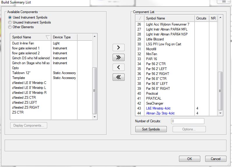
Oh, I think I understand. So to pass it back as I understand it, what he was saying was that I can use whatever parts (symbols) I want in the main symbol of the strip light, and the counting tool will count those as the same unit as long as their instrument name is the same.
so for example my zip strips are made up of three symbols named Zip L, Zip C, and Zip R. These should appear in my lighting symbol maintenance report as different symbol names but have the same instrument name, so they’ll be counted as one type of light in the instrument summary on my title pages.
I’ll try that when I get to work tomorrow. Thanks for both of your help!
-
On 10/17/2017 at 1:40 PM, markdd said:
That's because you haven't! When the parent symbol is inserted, the program automatically splits it up into the various parts, and calls it a multi circuit instrument. So technically its right. You will need to look for the parent symbol in the unused Instrument Symbols section.
Maybe I built the symbol incorrectly then.
I made a quick vid of me trying to get this working:
I really appreciate your help
")
-
22 minutes ago, markdd said:
Go the the build list and make sure that the "Parent" symbol is in the build list and the cell symbols are taken off the list. Click on the Parent symbol entry and enter 3 into the circuits box below. 3 corresponds to the amount of cells it needs to count to make one multi circuit instrument. All should be well after that and you should have the correct number of Zip strips showing.
You must make sure that the Instrument name is the same in all the symbol instances of this fixture though otherwise the plugin won't know what to count.
I hope that works for you.
Hi Mark,
Thank you. I
didtried that and I think we're on the right track, but vwx still thinks I haven't used the main strip light resource in my document despite dropping it directly onto the plot onto the position I'm referencing. The parent symbols (znested L, R, C etc) are not considered lights only the main symbols and have been removed from both the build list and the lighting symbol maintenance report.Once i figure out these, I'll fix the par56 strip symbols and the cyc lights I have leftover so just ignore those in the attached photo.
-
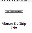
I'm trying to make my strip lights appear as one unit instead of each individual nested symbol in my instrument summaries. is there any way to do this? See attached image of how it's behaving now. I'd like the Inst schedule to just say "Altman Zip Strip 4ckt" with a qty of 1 and only show 1 symbol like it shows in my resource browser.
-
Solved: Turn off "Modify lighting instrument color" in spotlight preferences > Lighting Device.
-
 1
1
-
-
I'm having an issue where we were sent a light plot but no paperwork. So I've cleaned up their plot, imported my own fixtures, fixed label legends, etc. Finally ready to export data to make a LW. When I sync the info with LW and click back onto vectorworks, 90% of my lighting instruments lose their fill permanently. I can't swap their symbols out for new ones, change their fill color (they are nested symbols anyways), etc. However the symbols in the resource browser look normal, and I can drop new symbols onto the drawing and their fill is fine. I've tried saving the files to my desktop. Tried opening backup files from VWX and re-exporting, and I run into the same issue repeatedly.
Here's a video of the issue:
-
I've been playing with device types as of late and I'm having trouble distinguishing what each type does in relation to lightwright, and how each type is handled by vectorworks. I get that static accessories, when dropped on lights appear in LW in the accessory columns. That's great and I use it all the time. But how do I help VW and LW communicate regarding, say a gobo rotator? I guess it sort of comes down to designer and master electrician preference how they want it patched, whether its a separate instrument or they make it behave like a scroller (we use ETC consoles).
What's the distinguishing characteristics between the device types "light" and "moving light"? Does LW care about that?
-
A friend on FB recommended turning off tangent snap, and that seems to fix it. Unsure why but maybe has something to do with the CAD import and the fact that the line I'm placing the origin on is ever so slightly curved.
Thanks for your help!
-
9 minutes ago, JimW said:
Does this same issue happen in a new blank file?
It looks like you have Layer Plane active, do you have View > Unified View enabled?It doesn't seem to happen in a new file in the same way. it behaves the same way when I drop the line on the edge of a circle.
I do not have unified view enabled.
-
See video for description. I'm using the line to in vertex mode and the origin will not stay put. It's inconsistent, sometimes the line works fine and other times the line behaves as if it's rotating around a giant invisible circle in some sort of tangent mode. I've restarted vectorworks multiple times and this occurs in a variety of different files. This started when I upgraded to SP4 a few months ago.
What's the solution?
-
I don't know how to solve this issue, but I'd imagine tech support would want your version and service patch numbers.
I also don't usually use the instrument insertion tool, but I do use the accessory tool quite often. Running 2016 SP4 on windows 7 and no issues.
-
On 1/30/2017 at 11:35 AM, JBenghiat said:
The Instrument Summary filter option has simple check marks for filtering by position, layer, and class. You can also insert a custom criteria.
-Josh
Yeah, this has saved me 2+ hours of work. Thanks!
-
Anyone know how to fix a texture in a viewport that shows the wrong color? When I zoom in and out it momentarily appears correct but then reverts back to the wrong texture/color. Correct color is the color gradient on the right circled in red. wrong is the blue stripe on the left. I two viewports next to each other with the exact same classes and layers on/off. In the one on the left, the color gradient appears blue, and in the one on the right, the color gradient appears correctly. The symbols are exactly the same and are dropped on the fixtures as accessories.
I've tried replacing the symbol, turning on/off various classes, checking plane, class/layer assignments. I've had this problem in the past and normally it's a class issue but happens across all my viewports with that particular symbol.
-
Thank you! I didn't know about the filter option in the instrument summary tool.
Can you save that as a 2016 file? I'd love to see how that work sheet is set up.
-
Hi,
I asked this question a day or two before the new forums went live and my previous post has vanished into the nether.
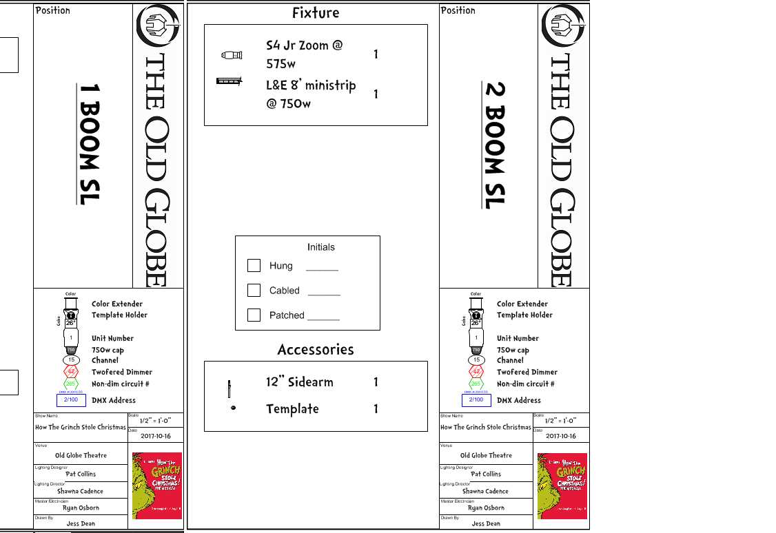
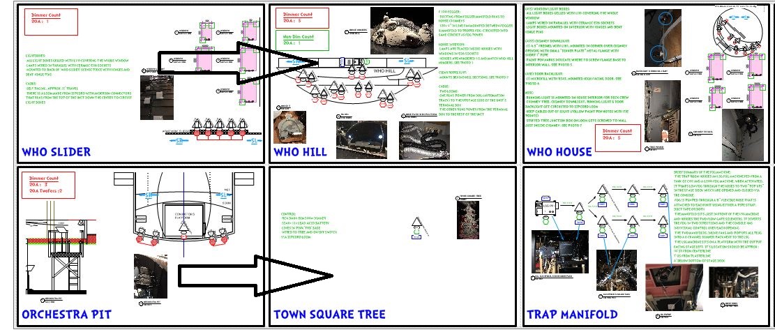
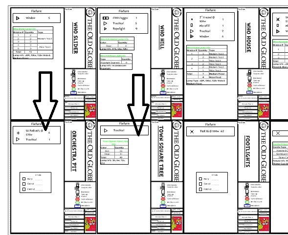
I'm trying to make a work sheet that when I run a script will import certain information from record labels attached to symbols contained within a viewport on a sheet layer. I want to make a list of lighting fixtures that exist in a view port, basically. In the attached picture, the red box is what I'm trying to do automatically. Currently, I manually enter all of that information which is time consuming and error prone when things change often.
I'm also trying to learn vectorscript and python, so I'm hoping someone can just point me in the right direction so I can learn how to do this.
Thanks!
-
Hi folks,
The scenic draftsperson often takes vectorworks files (2016 spotlight) and imports them into Auto CAD 2016 to maintain updated section and ground plans for shows we're working on. She's having a problem, however, where she can't delete the locii in cad that have been imported from the VWX files. I know this isn't a cad forum, but the locii show up when printing and they're undeletable/selectable and can't be assigned to new layers. Any thoughts about how to fix this without re-importing the vwx file without the locii?
-
I fixed it by remaking the side arm symbols. I copied the lines and polygons in the c-clamp symbol, deleted the c-clamp symbol out of the side arm symbol, then just pasted the c-clamp lines that I copied back into the side arm symbols and it worked. I don't...i don't know wtf. It works now, thanks for your help.
-
i highlighted the problem area with a big red oval.
For giggles I tried importing the 14 deg symbol from the ETC symbol file, though it should be be the same, and it did not fix the problem.
-
I will post the file soon.
-
The clamp sometimes disappears and sometimes doesn't, although selecting the side arm shows at least the outline. I've checked the clamp symbol and it's innards belong to the same class as the iron, which is also the same class as I use for the side arm accessory on the plot. The layer is the same layer as the fixtures.


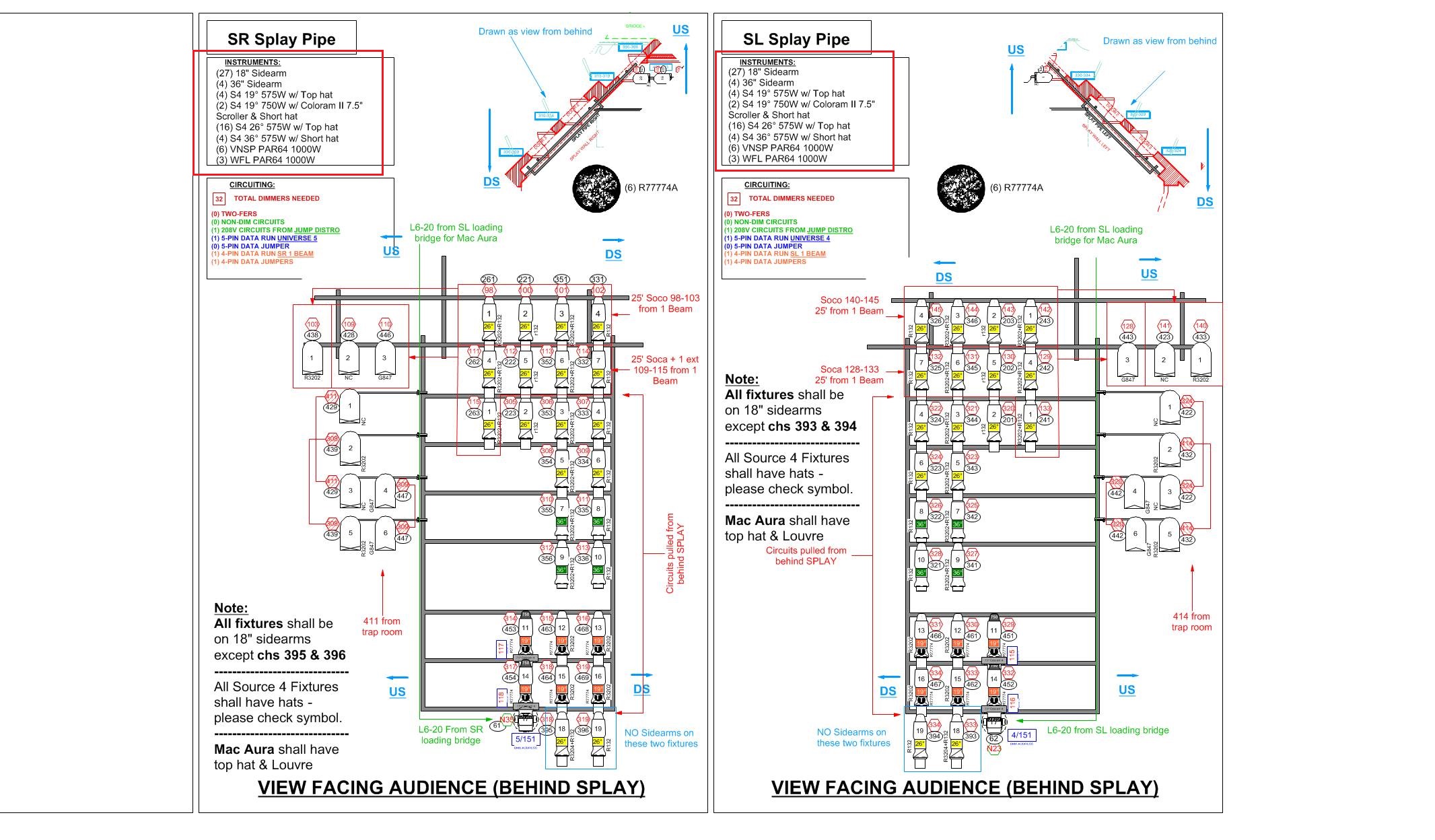
Instrument Summary questions
in Entertainment
Posted
See this post here. You will likely need to make an instrument summary symbol separate from the one used in your drawing.