
halfcoupler
-
Posts
464 -
Joined
-
Last visited
Content Type
Profiles
Forums
Events
Articles
Marionette
Store
Posts posted by halfcoupler
-
-
as described in the help files marionette commands can only be edited in the user/libraries/defaults/Marionette/Marionette Command Library.vwx file.
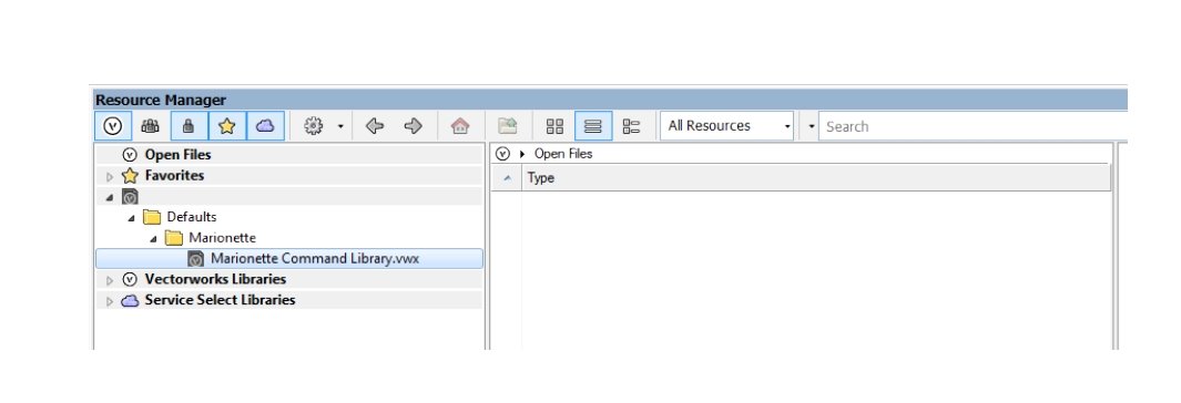
in my resource browser I see the following:

This file can not be opened from the resource browser, and there are no resources shown. I can only directly open it when navigating to it via explorer.
Whats strange:
I can't simply open the 2D symbol definition here, edit the Marionette and save the file. This has no effect on the Marionette commands. I can only open the the symbol, copy the marionette, paste it somewhere, edit it, wrap it, create a menue command and overwrite the old one by choosing the same command name.
Is that correct, or is there a more elegant way to edit marionette commands ?
-
Great ! Works perfect. Thank You !
-
Just found that I can run the Marionette from another design Layer, but the ojects will then be moved to that layer ...
-
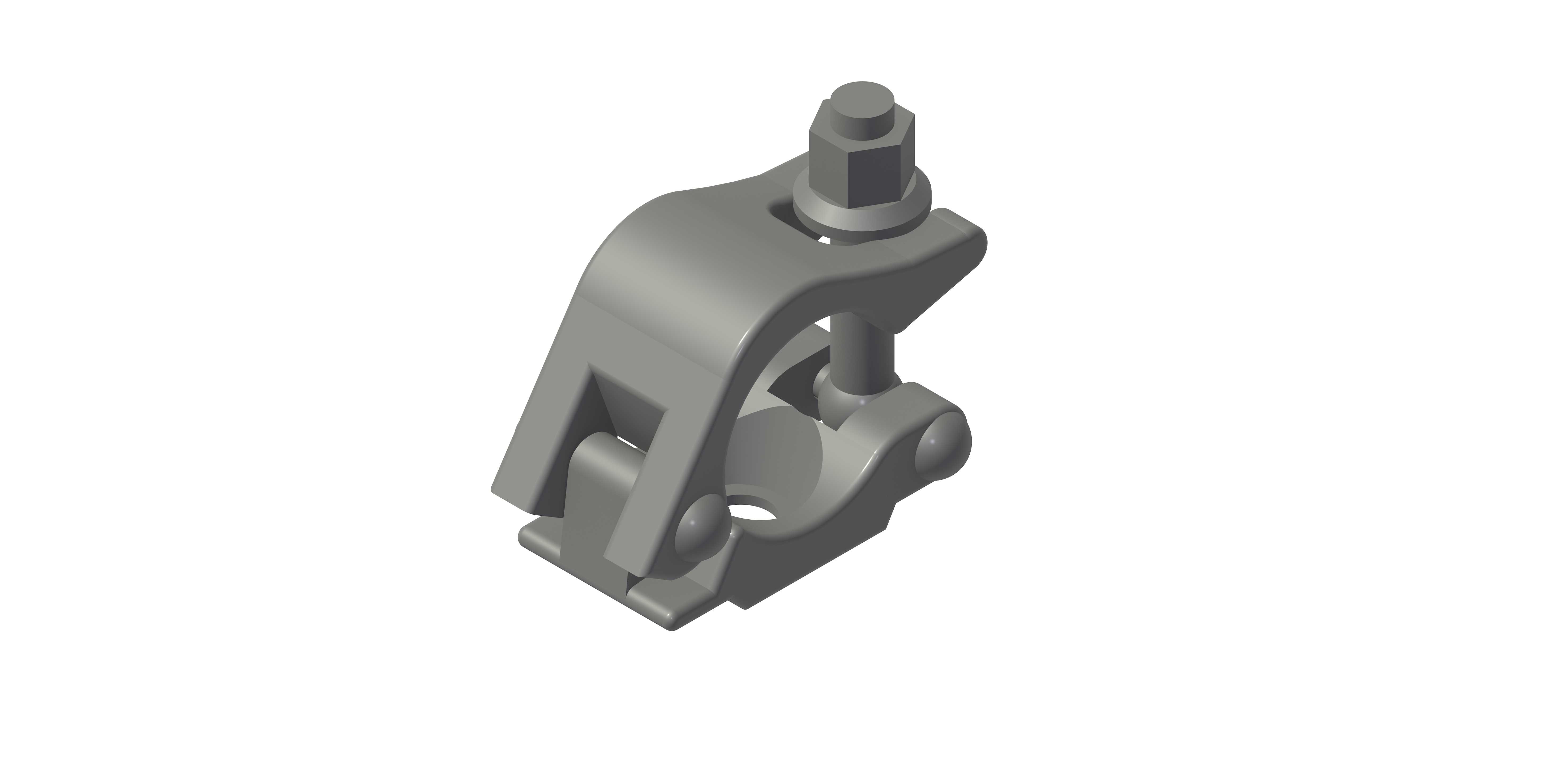
I have made a small Marionette that extrudes several path objectes:
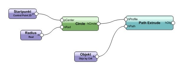
I have wrapped this and created a plugin symbol for this.
My default criterium is (SEL=TRUE) , so I want to select several objects and run the Marionette on these objets. This does not work: As soon as I select the Marionete, the selection of the objects is gone and vice versa... ( of course...)
Converting to a marionette Menu Command works fine, but I then I lose the ability to configure the criteria and circle raduis.
Choosing other criteria like pen forecolor or class works fine too.
Did I oversee something ?
-
Am I the only one ?
- reset tool modes in the reset save settings in the preferances dialog
- drag and drop a symbol from the resource browser to the drawing
=> import resources dialog pops up and asks for preseving folder hirachy
- chose "preserve folder hirachy" and "don't show this dialog when drag and drop importing"
=> What I am expecting is that from now on dragged symbols are imported to their respective folders without dialoge.
=> This is correct for this session.
- close and restart vectorwoks
- new file, open a template
- drag and drop a symbol
=> the dialog is NOT shown and the symbols are NOT sorted to their respective foldes from now on.
No chance to correct that without resetting all tool modes again.
-
Thank You Pat,
this is exactly what I need ! !
😀😀😀
-
Yes, as requested, worksheet is one solution, but it is not quick enough. I'm looking for something that I can use while drawing.
Background:
Basically it is a kind of tent construction that has to fit to an existing canvas.
I am searching for best design of lines, arcs, polygons and nurbs that match a certain perim lenght. It is a trial and error process in which I have to run through, since there will be several shape-designs that fit.
But I guess a function like this could be helpful for the Landmarkers too...
Maybe that is a Marionette task ?
-
Hi @all
anyone here knows the ultimate trick?
I have several lines selected somewhere on the drawing.
I want to summarize their line length.
Except adding the OIP Values manually or create a worksheet, what is the quickest way to get this value ?
Workflow should be something like:
- Select the lines
- do something
=> get result.
- choose other lines
- repeat.
-
Hi Pat,
right,
from a programmer's view this seems all logical.
From a users view this seems all unlogical, unless the user is a programmer. 😀
Since I'm only a "super-mini-mini-programmer", I have found my workaround for replacing existing record format values in a drawing:
What is NOT working:
- dragging a Symbol definition with new record format and/or new values to the drawing: This will only affect the symbol definition and the new instance, but not the existing instances.
- using the attaching/detatching tools from the Menue->Tools->Records: This tool affects only the symbol definitons in the file, and leaves the existing instances untouched.
- Replacing symbol instances with a symbol definition that has other record format(s) attached than the record format of the instances: This will result in adding the new record format to the instance(s) additional to the old one, which stays untouched. ( I am not shure, but I think somewhere there is a rule setting for that behavior about adding/merging record formats ?)
What works:
- replacing symbol instances that have exact the same record format as the new symbol definition, only with other values: The old values will be overwritten.
Hope this clarifies a bit for others who might stumble over this thread.
-
49 minutes ago, halfcouple said:
how can I teach my drawing to replace the record format for all instaces ?
ok, solved so far, as explaind in the help file:
- select the desired instances, select the desired record format, right-click => attach.
But this seems to be a one way road, field values of instances can not be overwitten by replacing the symbol definiton...
-
I wonder if this is a bug or if thats me wo does not understand how record formats are attached:
- drag a symbol with record format "A" attached into a drwaing
- replace this symbol via the replace button in the OIP with some other symbol which has different record format "B" attached.
Result :
the symbol is replaced, but the record format "A" keeps sticked to the instances that are already in the drawing.
I expect the record format to be replaced too....
If it's correct and intended that record formats are not replaced in this way, how can I teach my drawing to replace the record format for all instaces ?
-
Hi@taliho,
in 2020 there are several options to reduce file size. You have to set these for each sheet.
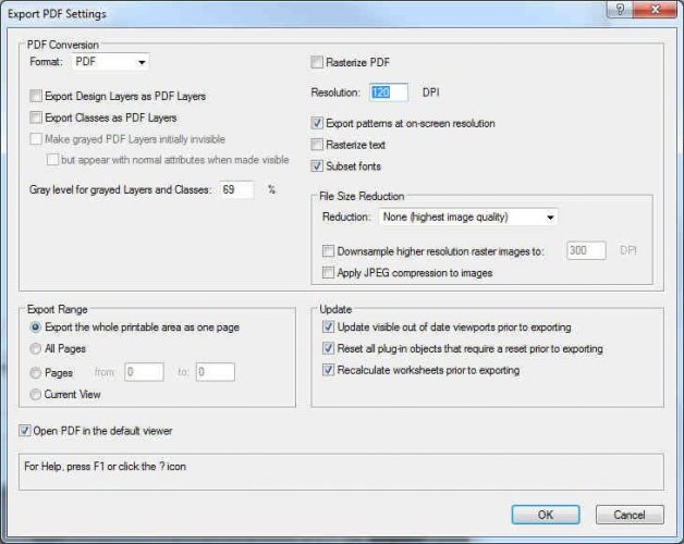
Here are my favorite setings:
- Rasterize PDF: This usually increases the file size. I use this option only in case I want to avoid that the PDF can be disassembled after exporting.
- Resolution: I'm using 300 DPI for good quality exports, 120 DPI for sample files and e-mail attachments.
- File size Reduction: I usually leave that untouched, unless I have embedded images (for example camera match objects) on my sheet. If used, I mainly use 300 / 120 DPI as above.
- Apply JPEG compression: alwas On when reducion is activated.
1 hour ago, taliho said:basically spreading the original viewports over 2 sheets.,
I suppose this is what increases your file size, I haven't checked this out, but I guess a larger viewport, especially when rasterized will increase the file size in comparison to a smaller viewport with the same content.
Hope this helps 😀
-
Hi Mark,
I have generally skipped using the Set View Button several years ago. Main reason was that it is not replicable,- after setting several clicks turning and twisting you dont know what you did and I always ended up with either doing dozens of undos or deleting and creating a new viewport right in the desired view, which I guess seems to be the quickest way to transform a Viewport to any other view than the presets on layer plane. Too bad the button "Working Plane Views" do not work in this manner,- it would be an intuitive workflow, similar to the general activation of a working plane. Another whishlist-topic ?
Thanks for your help 🙂
-
Hi markdd,
that was my first thought too, it should work that way, but it does not,- it's working only on design layers, not with viewports on sheet layers ...
I want to change this setting
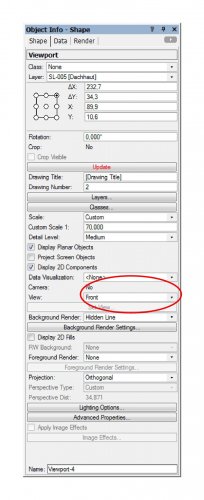
aligned to working plane.
The only way I found to do that, is to go to the design layer, activate the desired working plane, and create a new viewport. There seems to be no way to re-align an existing viewport.
-
Hi @ all
just stumbled over this:
the views offered in the OIP of a viewport (Top / Left Isometric / Right Isometric.... etc. ) are always according to layer plane. What is the quickest way to align a model in a viewport to a saved working plane ?
-
Hi markdd,
thanks for your help !
Yes, you are right, this is the "old" way to create section views, before clip-cube sections were introduced. You can even go one step further and put the section viewport on a design layer, edit the view and create a 3D-section-viewport. But this method is quite buggy: When the viewport very detailed it terribly slows down the whole file, I even got crashes with that.
My original intention was not to create a viewport,- I wanted to focus and work on a detail in the drawing, just as it can be done normally with the clip cube, but wanted to do this on the working plane, not on the layer plane.
-
Just now, _James said:
how are you able to check?
very simple and non academic: Observing what I do when drafting. 😉
After that, trial and error check if the choice was right .
-
I checked which functions I use most and put those on the mouse buttons:
- selection tool
- move by points
- undo
- redo
- open GL
-
 1
1
-
-
Ok, so this is a topic for the wish list ?
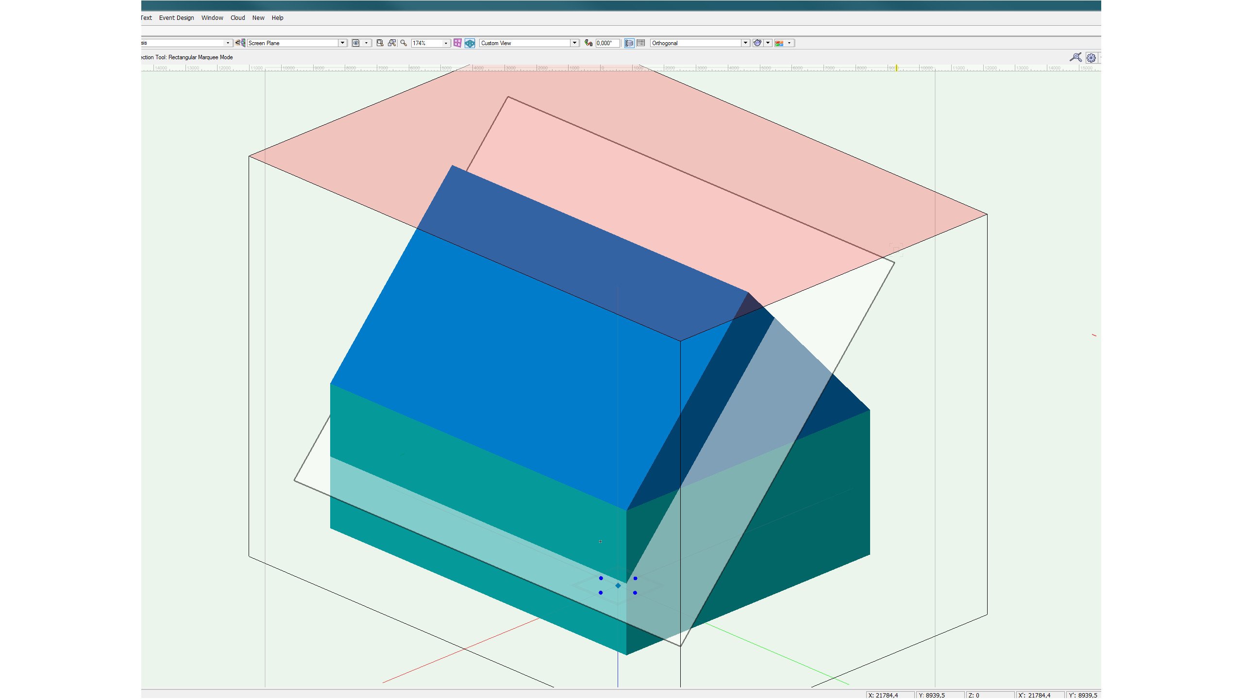
Wonder if I'm the only one who ever stumbled over the desire to create a clip cube section of a roof parallel to the slope or similar. 😟
Background: I'm creating a stage roof with complex rigging points and confusing truss structure, where a clip cube parallel to the slope and perpendicular to the working plane could be quite helpful with drawing details.
-
Hi Wes,
thanks for the reply 🙂
Hm, thats bad, since clip cube can only be rotated around the z-axis. So is there a workaround to get a section plane as shown here:

The only workaround I can imagine is to to rotate the the whole model, so the desired section plane is either parallel or perpendicular to the layer plane...
-
as far as I see the Clip Cube is always rectangular to layer plane, even when it is activated on an active working plane. Alignment can only be done manually by rotating. No way to align it automatically ? Is that right ?
-
Thank you much for your reply,
that's almost what I expected ... just wanted to be shure I diddn't oversee something.
-
Maybe that is a topic for the whishlist, but does anyone know wether there is a way to print the name of the publishing set on the sheet layers, or in their title block ?
I think the only way to achive this is to define a custom link field, but what is the definition ? Something like #publishing set# ??
-
As Pat explained, a worksheet can't know that it needs to be updated. Maybe a worksheet can be compared to an excel-sheet that is populated monthly with invoice data, which is exported from an accounts-package-software. The excel sheet does not know that a new month has begun or that there are new invoices that need to be exported. You have to go to the accouts package manually and press the button to export the data.


Editing Marionette Commands
in Marionette
Posted
Hi Pat,
maybe I was not clear enough: I dont want to edit Marionette Nodes, I want to edit Marionette Commands as is described in the help file
What puzzles me is
"If the wrapper node is not in the drawing, the wrapper node resource can be imported from the Marionette Command Library file in the Resource Manager."
but I can`t access this file from the Resource Manager.