Darnold74112
-
Posts
7 -
Joined
-
Last visited
-
Hello All, I have a file that when I perform the Data exchange into Lightwright from Vectorworks, Vectorworks does not include all of the X,Y,Z coordinates for half of the the fixtures. Any ideas?
-
Vectorworks Lighting Symbols and LW6 Data Exchange
Darnold74112 replied to Darnold74112's topic in Entertainment
@klinzey Just tried it in 2024 and still have the same issue. -
Vectorworks Lighting Symbols and LW6 Data Exchange
Darnold74112 replied to Darnold74112's topic in Entertainment
@klinzey Thanks for responding, As it goes, we do not add fixtures in LW. All fixtures are added in Vectorworks before adjusting parameters in LW. The lights do not have any accessories associated with them, Therefore not editing accessory info. Not sure if you noticed in the video, but when I applied the channel info to the units (which was done after the data exchange was initiated, the impressions that I made 501-514 did not get that info, when I searched for it in VWX using find and modify, it selected a Mac Ultra which is a completely different fixture that was in the 10's for channel numbering prior to the change which came from the exchange that thought it was editing an bar on a completely different truss When a drawing is received, We typically perform a full export in a folder that is not synced with a cloud on the computer itself. Then open LW and go from there. VWX is the one setting everything initially for the exchange. We also ensure that the exchange has all the parameters we use. It is weird that it works with some fixture and not all. The thing with deleting a fixture is you lose all of the information that they have put into the fixture such as channel, purpose, focus. Yes this is 23' as our designers are not ready for 24' just yet. The fixture symbols are pulled from the live library in the resource browser -
Hello Everyone! Recently a few Production Electricians, my self included, have been having issues with Vectorworks not taking the information and or fixtures disappearing in LW. With time I have come to identity that it has been an issue with specific symbols such as the X4 Bar 10 in this instance. Some things that are happening include the following. Lighting device symbol record will not take the information supplied by the data exchange from LW. If you change information associated with fields some units will take and others will be left blank on the object info palette then on another change, LW loses the information because VWX does not have anything in that field in the exchange. For some reason the dmx patch in VWX has channels associated with the symbols that are causing issues but it doesn't show that way. When looking at the Spotlight DMX Patch program, the sheet recognizes the x4 bar 10's have been channeled at 501-514 while the selecting the fixtures will not show the channel or patch information in the lighting device object info palette. It also has several additional fixtures that don't have any channel information which are un-locatable on the drawing itself. When new think we are editing a specific fixture, it appears as though the specific vwx id is duplicated causing vwx to assign what we thought we were editing and apply it to a completely different device in another location My current questions are. Is there a standard to which the symbols for fixtures are created now. Who is checking the GDTF? Are they tested multiple times to make sure that when inserting into a drawing, they are not corrupt? Last one, Help! Please, I have called support about this multiple times and I get the its not on us response. This is a vwx assigned id issue and not a mckernon issue. Video Attached. Thank you all for your time. Video of issue.mov
-
Instrument Summary - Text is Super Small
Darnold74112 replied to Darnold74112's question in Troubleshooting
Scott, Sent you a PM. -
Instrument Summary - Text is Super Small
Darnold74112 replied to Darnold74112's question in Troubleshooting
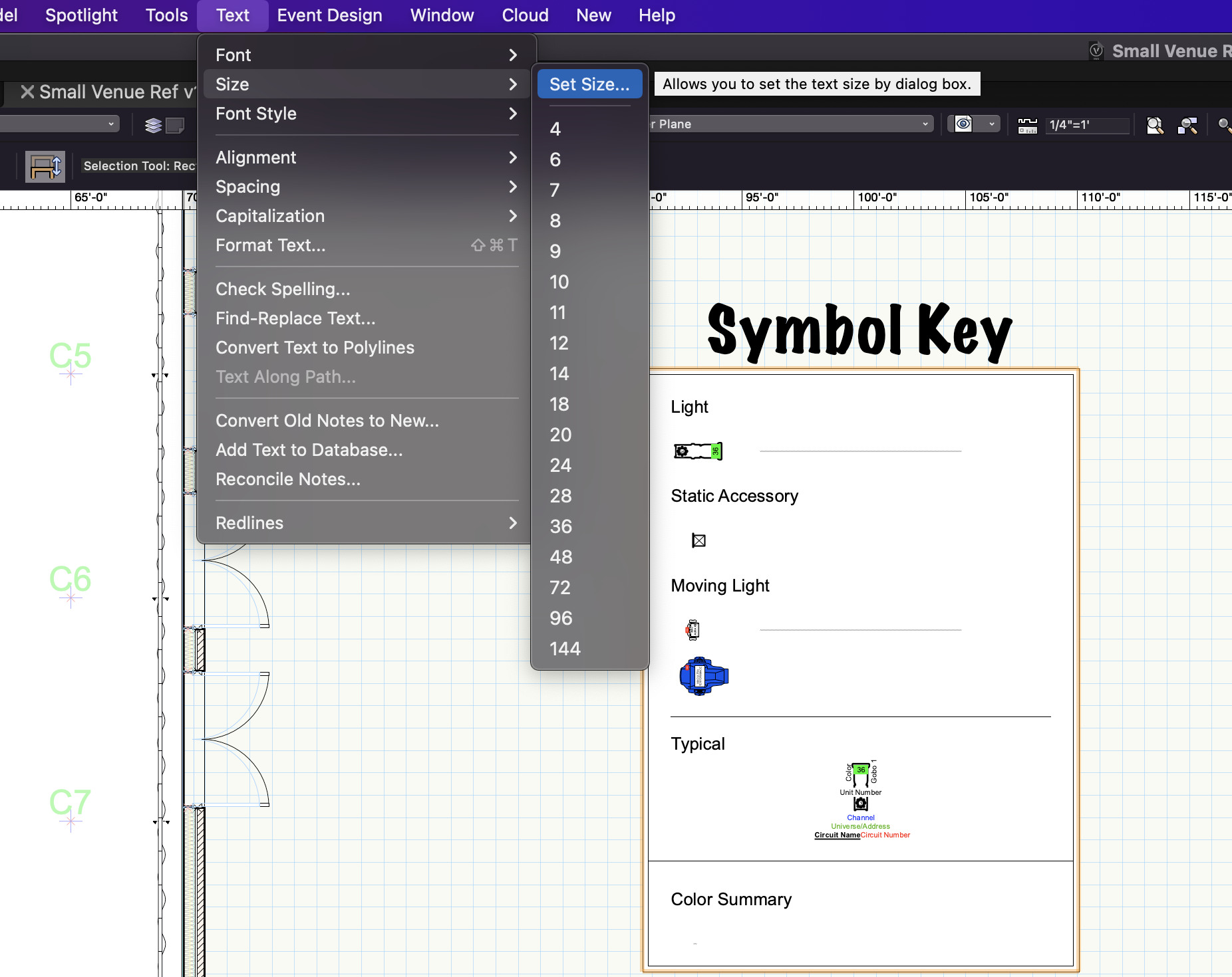
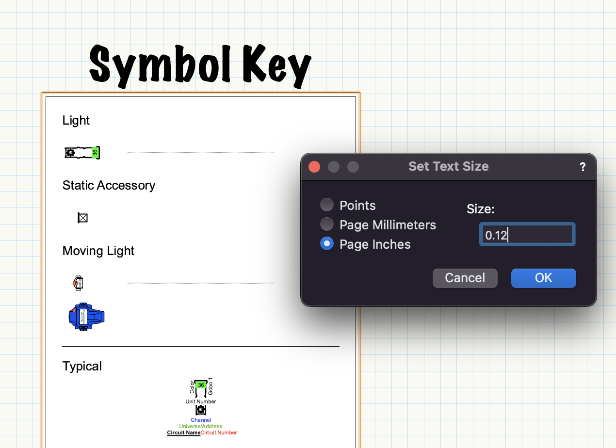
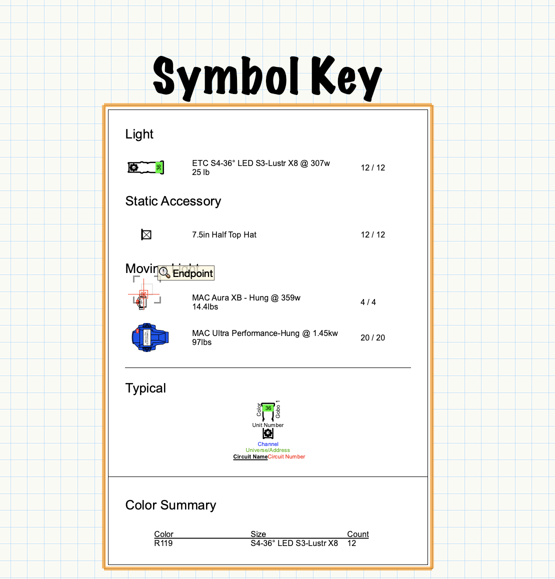
Well, It looks like I get to answer my own question. After digging around I decided to try accessing the text menu in the main tool bar on the top of a Mac screen. Hopefully this can help others who come across this problem. Order of operation 1. Select the Symbol Key 2. Hit the "Text" dropdown menu. 3. In the size menu, select "set size" 4. I used 0.14 for the size and it seemed to be just perfect.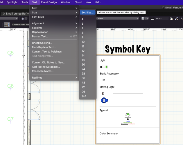

-
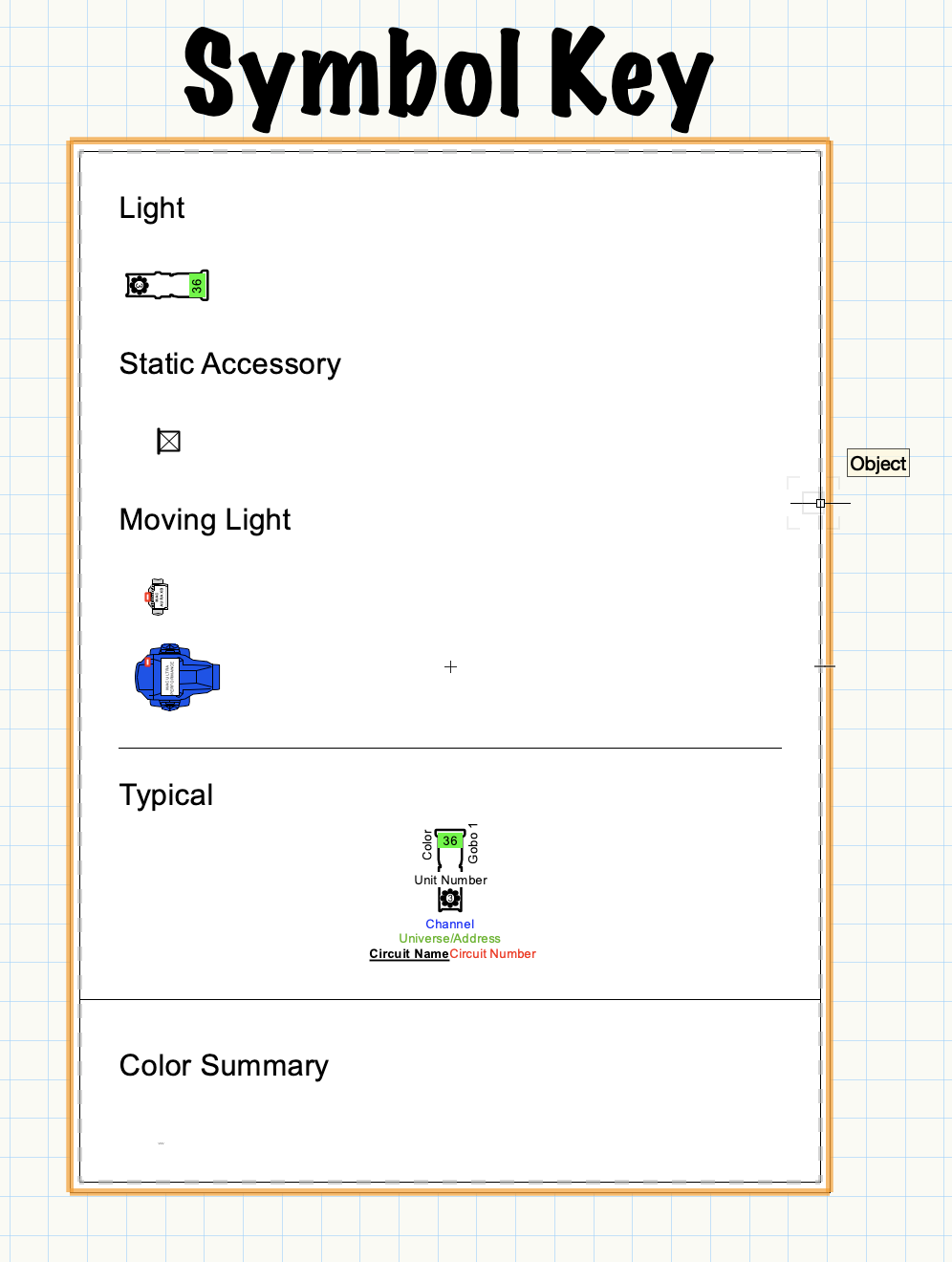
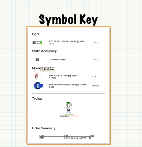
Hey all, When I prompt an instrument summary in my design layer the text that displays after an instrument symbol comes in at such a small scale that makes the text box it is in appear only as a line. See image below. There appears no way to edit the summary text in the OIB. Any one have any ideas? Thanks!