


thinkingpencil
-
Posts
108 -
Joined
-
Last visited
Content Type
Profiles
Forums
Events
Articles
Marionette
Store
Posts posted by thinkingpencil
-
-
Thank you virtualenvirons....insightful. I will report back.
-
Whilst using the Extrude Along Path tool....I was editing the path. Causing the profile to reverse. So instead of my cornice facing outward over the wall face it faced inward. But I had not edited the profile. This problem was solved by editing the profile which was still located in the orginal path position. So by moving the profile to follow the new path vertex...just sayin'. But then I still haven't started to use 2023.
-
Tom W. thank you for taking the trouble to explain this so clearly.
-
 1
1
-
-
I found this topic whilst trying to make a horizontal section viewport render certain layers in an override colour. Couldn't do that (not sure why maybe you just can't? But I could render colour by class override)...
...but thanks to Tom W. 's suggestion I achieved the desired effect with a data vizualisation. Thank you Tom W.!
-
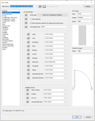
To simplify a section-viewport I wanted to show just frames not door leaves. In settings for the plugin door object, 2D visualisation, I set the leaf to a class different to the object's class. Then set that class to invisible in the VP. But the leaf still showed in the section viewport. But not on the design layers. A further setting is needed. I think because the leaf is framed. So in the plugin settings, classes, the stiles and panels have also to be set to the class which is off in the VP....
-
Update. Having rationalised both 2D and 3D classes all doors are rendering as desired. I now have a deeper insight into the awesome controllability of the Door plugin object. For example a flush door leaf has an intrinsic external panel enabling two colours inside/out.
...and finally :- The filled arc was eliminated by changing fields in the 2D Visualisaton tab of the plugin door settings dialogue. To be precise :- With "Set Attributes by" set to Class" / "Wall Lines" set to class called "Doors-Wall Lines". Crucially the arc of fill disappears because this class is set "Graphic Attributes" / "Fill" / "Style" set to "None".
Workflow back on track for tomorrow's deadline now. Thanks to your crucial guidance Tom. It's 21.06 so off to celebrate with a beer now in the pub!
-
1
-
-
Thank you so much Tom. It is kind of you to spend time looking at my file. That sounds like excellent advice. Will do. Mark
-
1
-
-
...one further observation...the door inserted into the wall seems to have a problem. For some reason the flush leaf is splt with half its thickness in the same colour as the arc-fill. Trying to unravel this door setting too!
-
VWX 2022 SP5
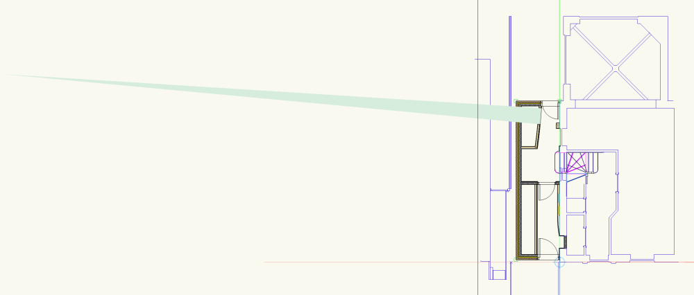
A door PIO causes a filled arc of radius equal to the radius of the round wall. The same result when the plugin is is set to "opening only". The filled arc is not visible on Top view...but is visible in a horizontal section VP. Any help or observations gratefully received. Tthe colour of arc-fill is random, so not related to the classes of wall, components or the door itself.
-
Thank you Elite Exhibits. Will do!
-
Hi Matt,
I believe you are right in saying SP4 fixed this issue. I upgraded from SP2 (in use when the issue showed itself) to SP5. Using the same file I cannot now reproduce the issue, all is as expected. However I have attached the file which was missing from the folder we tried to share. Probably for academic interest by now. Thank you for your kind attention.
-
Hi Pat,
I tried to reproduce the issue in the same file. Now finding the issue does not exist. Having said that the exceptional number of sheet layer VP's in it may mean I simply couldn't find the VP in question. (Many VP's because unusually I was asked for steel production drawings and so used the steel frame model to generate a full set of four 2D elevations of each member. I mention this incidentally because without VWX's modelling capability there's no way I would agree to do such drawings. I am not a structural engineer! But I can now produce very precise drawings).
Also the only difference between the file in operation on August 2 and now is that it was opened in VWX2022 upgraded, finally, to SP5 after Aug 2. So maybe that is significant.
I am sorry not to be of further help.
-
Matt Panzer
Your really helpful attachment finally prompted me to use data visualisation! Thank you.
And I intend to return to our conversation about walls....
-
1
-
-
....PS!...of course the obvious conclusion is that the notes database is replaced by the VWX file template which contains wall styles with wall style/data tab/description fields being the source of specification.
-
_James
I agree, to create your clear and well organised plan with more automation would be welcome. In particular the facility to call up text from a notes database in, say, a wall style/data tab/description field. At the moment I do this manually, pasting such text copied from the notes database. Then of course I would have to update the wall style field manually if the notes database is changed. I guess use of IFC would be the way to do all this automatically....but I haven't explored that yet.
I am creating a version of your plan by, yes, tagging one of the several objects sharing the same wall style. The tag is a custom record format which enables me to call information from the wall style/data tab/description field into a worksheet. I then add a key colour which is the same as the data visualisation colour for that wall style. So the worksheet is on a sheet layer beside the VP with data visualisations switched on....
....the refinement of yours I lack is the <100% opacity which shows wall detail through the DV colouring. But I will probably do this for 1:50 key plans and then show detail in 1:10 or 1:5 etc detail VP's.
Thank you for sharing.
-
Hi Matt,
I have uploaded the file to this VCS folder.
After reading your earlier advice I moved the wall to reset. But no fix.
I will use SP4....just been extremely busy! I am the CEO, IT Manager and the guy who cleans the office here!! A builder announced he was starting on site early, after a contract cancelled..so I had to deliver the construction info v quickly...not good at saying "No"....
Thank you for engaging. Good to see you in action after last year's summit which I really enjoyed. Off to cycle now. It's 18.40hrs here and 29 deg...v hot for Macclesfield, England.
Regards,
Mark
-
Hi All,
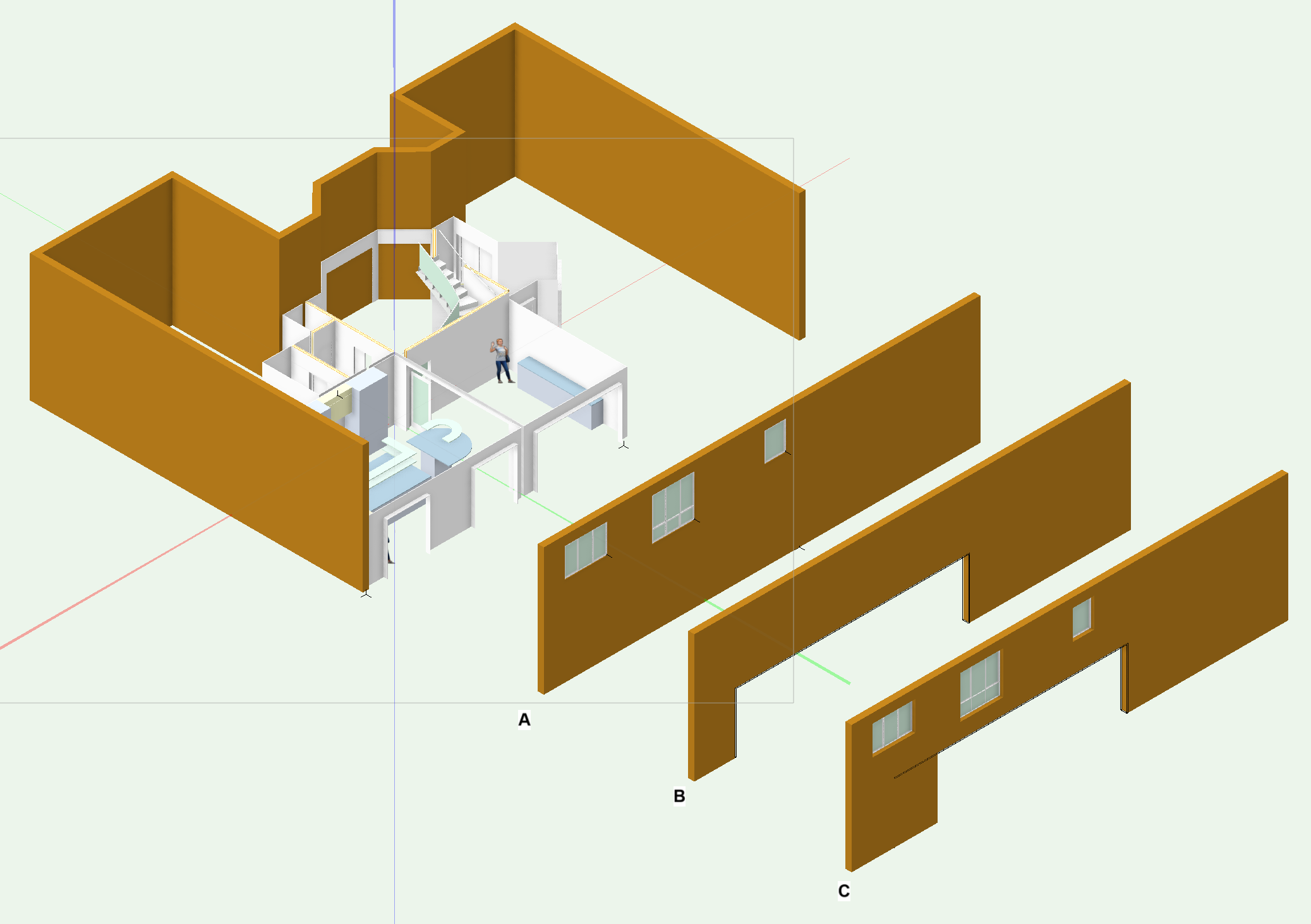
The attached (Architect 2022 SP2) shows this problem I think. Referring to the screen grab:- The middle-sized window (left hand side) has some wall down to level Z=0 associated with it. This wall is not removed when the cased opening (bottom at level z=0) is inserted below the window. See C. But the other two windows do not "randomely fill" the cased opening with wall in this way. Yet all windows are settings= except for size and frame variations. Put another way if you move the cased opening away from the middle-sized window the full wall hole appears. The opening and one of the windows cannot co-exist in the same wall!?
I'll work around this by using both A and B:- Setting bottom offest of A and top offet of B so that they render as one.
By the way I haven't designed this house. Which was "designed" by a builder. Client's won't demolish. So I am trying to add some star quality with the usually wonderful VWX!
-
Same problem as MHBrown.....but my file has many VP's, far more than usual...
-
I created a 3D symbol including both a window sill with a 3D wall hole aligned with my window. (Preferring this modelling method instead of using the VWX window sill function within the window tool...so the window is not inserted into the wall and is separate from the sumbol). Then needed to edit the 3D wall hole. The result was a symbol with two wall holes. But only one, the edited one, was visible in the symbol definition. But...apparantly at random whilst trying to fix this the second 3D wall hole did appear at one point and could be deleted. I say random but I checked/unchecked "ignore wall closure" during my trial fixes and maybe that had an effect....anyone experienced anything like this?
-
...Yes a big subject. Thank you again. I am looking forward to learning more. And will check out those references. Meanwhile I remember a fellow student of architecture whose final thesis featured tent structures like the German engineer Frei Otto's. He learned some basic rules of design by studying Otto's 1972 Munich Olympic stadium.
I remember those rules were all about sag, curvature etc etc
I am meeting him soon and will pass back any advice on them.
PS the video at the link is not HD for sure! But then in the seventies the fax machine was yet to be invented...
-
1
-
-
Thank you all for this excellent thread. Benson I followed your workflow successfully. Thank you again for such clarity. I am posting here to offer a small point:-
Comand :- Model>3D Powerpack>Create Surface From Curves did not always work.....why? I think because the directions of the nurb curves were not all clockwise. As soon as I changed two opposing directions to follow one another and so all curves had the same direction then the comand worked.
-
2
-
-
Like David I had the same problem of a model unlit by a heliodon, no obvious reason. (Another H was 100% functional in the same file). Thank you HEngineering! So I deleted and replaced, no problem then. Glitch?
-
1
-
-
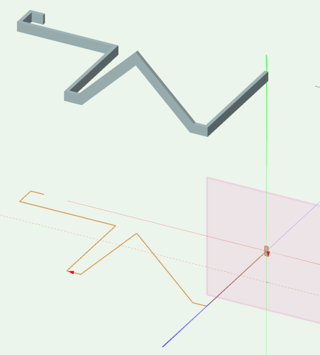
...EAP is challenging...for a path in all three axes I am finding the 3D polygon tool is best.
-
1
-
-
The advice above to be careful about path direction is SO important. I find all goes well if:- Directions and working plane are as below. And the profile is a polygon not a rectangle (in this workflow). Worth practising in my view. Saves me time now I used this complex command more often.
-
2
-


Section lines that can bend, not just step
in Wishlist - Feature and Content Requests
Posted
I drew four sections each from its own section line. The section lines were joined at angles on plan different to 90deg so that they cut through the buildings on my block site model orthogonally (buildngs not orthogonal relative to eachother). I also drew a simple horizontal "reference datum extrude" across the entire model to enable each viewport to be easily aligned in elevation. That extrude's class is later set invisible in VP's, obviously. I drew a polygon from the section lines and pasted that into one of VP's annotations plane to help align them horizontally. Again set invisible afterwards. The model is accurate enough to render with conviction in, say , an aerial view. But messy in the sections. So the final composite of four VPs will rely on 2D graphics in annotations, with the messy graphics set invisible.
....so yes I am also waiting for a tool which draws a polygonal section line then creates one Section-VP. I'd be happy with just the information along the line. With no view of objects beyond or behind the cut plane. But that's because I seldom design buidlings without orthogonal plans. And the composite VP I have just made is of a simple site block model.