


line-weight
-
Posts
3,756 -
Joined
-
Last visited
Content Type
Profiles
Forums
Events
Articles
Marionette
Store
Posts posted by line-weight
-
-
Try this, Create an elevation viewport and then select the viewport and draw a sectional viewport over the middle of the windows of the viewport. From outside the viewport so you cross over the entire viewport and face it down.
The result will be a plan cut at the middle of the building which includes all the sloping walls looking down on them.
HTH
Yes, have already done this, thanks. See the last image in my initial post. The problem is that this doesn't show doors symbols etc properly.
However, I think I might try using a design layer viewport (that I can switch on and off) with this sectional view, that I can trace off in 2d to get my cut lines in the right place.
-
Thanks for these replies. They seem to suggest an approach similar to what I was deciding to try out.
So for each building level I need 3 types of elements
a) 3d/2d hybrid objects (display in 3D views and floorplan views)
b) 3d only objects (only display in 3D views)
c) 2d only objects (only display on floorplan views)
Any thoughts on whether it works better to separate these by layer or class?
eg. at the moment I have 3 wall classes (external walls, internal walls, party walls) because it's useful to be able to switch off, say, external walls whilst working on the 3d model. But if I also want to have these on or off according to floorplan/3d view, I have to subdivide each of those classes into my (a)(b)© categories above. So I end up with 9 wall classes instead of 3.
Alternatively I keep my 3 wall classes but have 3 floorplan layers, one layer each for type (a)(b) and © objects.
I guess separating by class probably makes editing things in floorplan view less fiddly?
-
I'm trying to make the switch from basically drawing in 2d, to making more use of VW's 3d capabilities. So I'm using a small project as a test run for this.
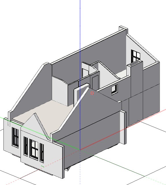
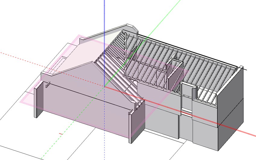
Here's what the 3d model looks like so far (with roof on and off).
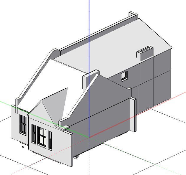
So the questin is, how to make a usable floorplan for that uppermost storey, which is largely within the roofspace.
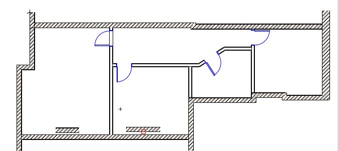
The floorplan (in top/plan view) looks like this:
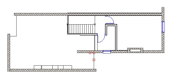
But that's no good, because it doesn't cut the horizontal section through the walls intelligently - for example the gable walls look on the floorplan as if they are full height for their entire length. And it doesn't show a cut line through the roof at all.
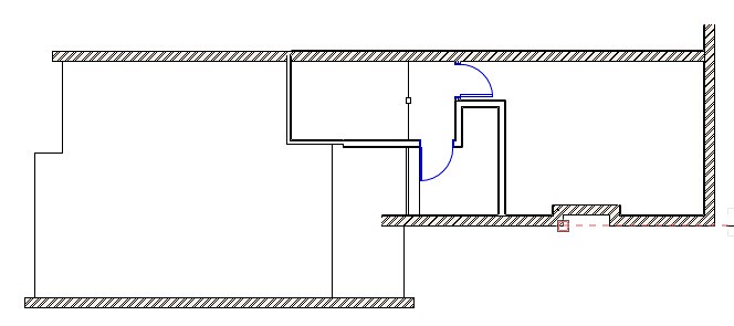
So, I realised that you can generate a "horizontal section" which produces this:
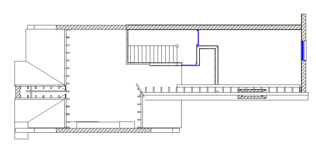
And (ignoring the messy bits of the model) that's more like what I want to see, and closer to what I'd conventionally draw for this kind of space, because it needs to have some indication of what the roof is doing, and where you run out of headroom and so on.
But this doesn't render the doors and windows with their proper 2D symbols, and there are mitred joints in the walls, and it's not really editable.
Is there a better solution to this, or are we confined to drawing floorplans as if the cutting plane is just above floor level (rather than at something between waist and eye height as per normal drawing conventions)?
(I should mention that I'm only using VW2011 at present)
-
Ah, sorry, I didn't look at your previous screenshot carefully enough. I see what you mean.
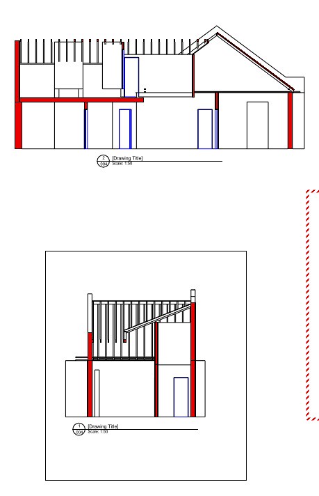
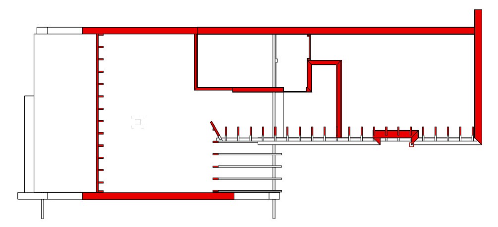
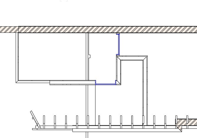
This is maybe a bit messy but might work. Once set up you wouldn't have to change any object's class or fill to render the section either way.
Create two identical section viewports. On one, set it to merge everything and fill using section style A (light grey to match your example).
On the other viewport, turn off "display objects beyond view plane" and then turn off all wall and slab component classes except for whichever components you want to display as the core, dark grey elements (So in this viewport your floating floor, ceiling finish etc simply is not shown).
Then stack the viewports exactly on top of each other and you get what my second screenshot shows. In my case I have coloured the timber joist zone in the floor, and the brickwork of the wall, the dark "core" colour. The only reason they don't join up and merge is that I haven't got my slab/wall junction set up properly.
My third screenshot shows the two viewports offset from each other.
Could this work? In theory you could stack more than two viewports if you wanted to have more than two levels of distinction.
-
Christiaan,
(have scrubbed my initial reply since fiddling around with my drawing)
Having drawn in VW mostly in 2d for many years I'm trying to make the transition to using the 3d model more, and to generate plans and sections from that.
The attached screenshots are from a messy and unfinished model which I'm using as an experiment but does the second one show the sort of thing you're after? There's no need to change the classes or fills of anything in the slabs or walls themselves - it seems you can have a dedicated class you can set to have the lineweight and fill properties you want to see in your sections (in my case that class is named "section style").
-
Ok. So, a year and a bit on I'm going to try and re-activate this thread and hope that some of you who commented above are still around.
A while back I moved from VW2008 to VW2011 (managed to get hold of a second hand license).
I've not been using its 3d capabilities until now, though. I have a small project which I thought I'd try setting up as a proper 3d model as a bit of an experiment.
It's been a bit painful getting Vectorworks to do what I want in 3d, having become accustomed to using Sketchup for the past few years. However, here's the (incomplete) model I've made so far.
The lower floor plan is fairly straightforward. All the walls are vertical and I've made them using the wall tool with multi-layer buildups and so on. Works ok (until now I've never really bothered with the wall tool, just done it all manually).
And I've managed to generate some sections which seem ok in principle (obviously the drawing is incomplete at this stage).
The upper floor however is more complicated because it's partly in the roof space. I've used the wall tool wherever there's a vertical wall. As you can see on the isometric I've managed to work out how to give wall elements a profile along the top edge (this was very fiddly though), on the two gable walls (which are in fact party walls; this is a mid-terrace house). And I've managed to draw the basic rafter framing etc (I did this by direct modelling).
But the upper floor floorplan doesn't look so great. Here is what it looks like at the moment:
Normally if I was drawing (in 2d) a floor plan for a roof space like this, I'd choose a notional "cutting plane" height, and this would cut through the plane of the pitched roof and so on. But Vectorworks doesn't seem able to take my direct-modelled roof elements and project them onto the floorplan in this way. It doesn't even seem to know to cut through those gable walls once they drop below a certain height, as they do when they approach the external wall.
So I looked to see if it was possible to cut a horizontal section, in the same way that you can cut a vertical section, and it is - I get something like this.
This shows the cutting plane properly, as I'd normally draw it. However, unfortunately I now lose the functionality of the door symbols - they are shown as a section through their 3d model rather than as a floorplan symbol with swing line and so forth. And the wall joins show up as mitred. This remains the case if I try rendering that same horizontal section to show wall build-ups etc:
This can't be an issue unique to me. What's the normal way to deal with producing a floorplan for a space like this?
It provokes in me the scepticism I expressed at the beginning of this thread about the practicality of using 3d models to generate floorplans and so on...as soon as you stray beyond the built-in limitations of the standard parametric-type elements evetything starts to fall apart and become more hassle than it's worth. But I don't want to give up on making things work this way as I can see the amount of tedious labour saved in drawing the sections alone.
digitalmechanic you posted a couple of your youtube videos earlier in the thread, and I've had a look through quite a few of your others. You seem to have had success in making 3d work for non-standard details (and share my scepticism about parametric elements), and I get the impression that you've had to work out how to get around the same kinds of issues that I'm puzzling over. So I'm hoping you're still looking at this thread and might be able to give some pointers.
-
Thank you - having the two viewports layers like you suggest works well. Problem solved.
-
So this is quite a common situation drafting in basic 2d.
Say I have two design layers: ELEVATIONS and PLANS.
I draw the plan, then to draw the elevations, on the ELEVATIONS layer I create a viewport containing a crop of the PLANS layer, and I use this to manually project the elevations from the plan.
But then, I make some changes to the elevations, and need to update the plan with these. So ideally I'd create on the PLANS layer a viewport containing a crop of the ELEVATIONS layer, again to project manually from elevs to plans.
But VW doesn't like this because that ELEVATIONS layer already contains a viewport of the same PLANS layer that I want to put the viewport on, and sets up a circular data cycle. This happens even if the viewport is cropped such that it excludes any viewports on the source layer.
Is there any way around this, or a better way of doing waht I'm trying to do (short of drawing everything in 3D)?
A sort-of workaround is to temporarily change the visibilities of layers in the viewports on the source layer, but this is a fiddle especially when drawings become more complex.
-
Using the reshape tool just does the opposite - the marker moves but not the text.
(I'm on VW2011)
-
(VW2011)
All I want to do is alter the length of a section-elevation marker - however when I select it and resize it using the pointer tool, the text in the marker at each end moves but the markers themselves don't. In other words the drawing/sheet number is no longer inside the marker circle/arrow.
I'm sure I've done this before without any issues. Can anyone suggest why this might be happening?
-
I can add a drawing label to a viewport on a sheet layer. It's useful that they automatically number themselves and that they automatically show the right scale.
However, it seems that for those things to happen they have to be added as an annotation to the viewport.
The problem with this, is that if I then decide to re-crop the viewport, or rotate it, or move it, the position of the drawing label stays relative to the viewport rather than the sheet. So any time I make any adjustments to the viewport crop/scale/rotation/position, I then have to go into the annotations and sort out the drawing label so that it's in the position and orientation I want (and usually all I want is to get it back where it was before, on the sheet).
It's not just drawing labels but also eg. scale bars and north points - generally if you are adjusting viewports on a drawing sheet you want all these things to stay where they are relative to the sheet.
Is there some way of getting around this problem? Am I doing something wrong?
-
I would have guessed that eye fatigue isn't just about overall brightness, but how easy it is to focus.
Kindles and similar devices designed for long periods of screen viewing seem to have opted for black on white, rather than vice versa. Is that because it's easier to focus on black-on-white text or just because it mimics printed pages and therefore people feel more comfortable with it? I dunno.
I'd have thought that more contrast would be better, therefore white on black better than white on mid grey.
I seem to remember reading somewhere that your eye finds it harder to focus on blue light than others (I think this is noticeable when you see blue lighting at night) so perhaps we should avoid asigning blue to too many classes....
-
I tend to have my screen background set to black. This is partly through habit (the background was black in the early days of Autocad etc when I first started using CAD) and partly because of a vague belief that it's easier on the eyes.
I've been wondering if I should start using a white background, because as soon as you start adding hatches, shade etc to a drawing, viewing it on black doesn't give a very good representation of what it's going to look like on paper (or PDF for that matter). I've found myself in an awkward compromise where I work on the drawing on black, but then view the sheet layers on white when it's getting close to ready for issue.
I can't find much info on whether black or white does make a difference as far as eye strain is concerned. Is anyone aware of any evidence either way?
-
I'm resurrecting this 5 year old thread to see if anything's changed in the meantime. Is it still the case that it's not possible to easily generate a drawing issue sheet (except perhaps if you are in Australia)?
-
Thanks for comments/videos above, interesting.
I think I need to try doing a small trial project using modelling to get my head around how it all works.
-
I guess I have a couple of questions. How "accurate" do you feel you need to be when representing an old building?
It's a good question - sometimes the answer is not very.
But there are situations where a lean or budge or tilt in a wall can become significant.
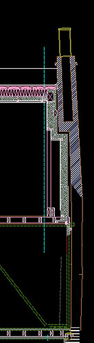
This is an (incomplete) section through the gable wall of my flat. It's about 150 years old and has a bulge in it, and the chimney leans over. This is not particularly unusual in London. The deviance from the vertical of that wall is around 100mm or 4 inches, within the height of a room. That becomes significant when you're trying to plan things in a tight space. In my case I was adding insulation on the inside, and creating a vertical internal wall meant stepping between different thicknesses of insulation. There are drawings which show this.
It's also useful to have a drawing which accurately shows the bulge in the wall for discussion with structural engineers, for example.
Even if I were to ignore that 100mm varience (which might be reasonable in many situations), if I were to draw the upper and lower floor plans, with a nominal section cut line at around waist height, say, to represent the avrage dimension of the room, then that wall would be in a slightly different plan location in each. That might not matter for the plans but if I then use that information - assuming vertical walls - to generate a section, it's going to look wrong because it'll have a step in the outside surface of the wall which plainly isn't right.
-
col37400,
I'm getting into this conversation late, but wanted to give you my opinion of drawing in 2D v. modeling.
I work at a small remodeling company and was also doing everything in 2D. I'd draw my plans and create my elevations, etc. all with polygons. I had done it that way for years in VWArch/RW, and became good at creating fast drawings.
Fo me, the problem with a 2D methodology reared it's ugly head whenever there were changes, whether from the job site changing (being incorrectly measured in the field) or from a client change. It was also very time consuming to present multiple designs during the conceptual phase.
Beginning with VW2011 (I'd used VW since v2006 I think), I decided to give modeling a try and invested in training. After doing 2 to 3 2-hour training sessions (using skype and screen sharing), I felt proficient enough to jump in. I've never looked back. In fact, I find it difficult to believe that I ever used the program as a 2D drafting system to begin with. I'm able to use layers to present different concepts within the same space. I get all of my elevations from section viewports. I use the time I've saved to do more with the overall presentation. I submit modeled drawings to my cabinet company to clarify details on custom pieces. I can demonstrate the differences in compound moldings to clients. The list goes on and on.
By switching layer and class visibility on and off within the viewports, I'm able to copy and paste viewports to get multiple drawing very, very quickly.
I think the key is to invest not only in the software (I'd go latest and greatest), but also in the training. You don't necessarily have to buy training, but I assure you that you'll consider it a great investment if you do.
In my humble opinion, modeling in 3D and getting your 2D drawings from the model is by far quicker and easier.
Good luck!
EDIT: I should've included this info when I originally posted. My trainer was a fellow community member here, BCD. He was really able to break through the mental walls I'd built up against using VW in 3D. Very knowledgeable, and I recommend his training services whole heartedly. You can visit his profile here: Excellent Training
Your experience sounds promising. And point taken about investing in a bit of training.
There are various scenarios where, in the past, experiments with 3d-based drawing generation have shown its shortcomings and made me decide to stick with 2d.
For example, drawing old buildings where nothing is straight. Can it cope easily with walls where the thickness varies horizontally or vertically, or which are leaning over?
If I have projects where, say, all the windows are non-standard, do I have to create them from scratch in 3d or is it straightforward to adapt standard ones? And do they have to be drawn in full detail from the beginning, or can they be modelled in a simplified way during the early stages of the project, and still look ok on the drawings?
Again where I'm dealing with existing drawings: sometimes no matter how detailed your survey, floorplans don't quite match up from level to level. In 2d it's possible to fudge this a bit, where it doesn't matter (for example if the bit that doesn't quite match up isn't relevant to the parts where you're doing work). But in 3d would I have to laboriously tweak everything so that the 3d representation didn't have bits where, say, stairs didn't quite match up properly, and hence generate 2d drawings where things look wrong?
Maybe I should download the 2015 trial version and have a play around.
-
comments on 2d projection drawing system compared to 3d modeling
Yup, that's pretty much exactly how my drawings are laid out at the moment! I'd gladly leave all that messiness behind.
-
It's architectural drawings that I do.
At the moment I've the choice between spending about £650 on VW2011 Designer + Renderworks, or about £2000 on VW2015 Architect.
Is the 2015 version worth the extra cash? Are the differences significant?
-
This is a complex question - while there is some very real truth to - if it ain't broke don't fix it - the nature of software / hardware compatibility occasionally necessitates upgrades.
I do VW consulting and most of my work revolves around this very issue. I would be happy to speak with you in depth - learn more about your situation and help you make this decision.
Feel free to write me an email - tklaber@gmail.com
Thanks. I may email you tomorrow.
-
I feel your pain. I am able to crank out 2d drawings rather quickly um err, using brand "x" software. But I was tired of lines and arcs and generating sections and elevations is quite labor intensive. The tools in VW architect were very appealing. I love doing plans with the wall tools and associated file tools. I struggle setting up the model correctly so that elevations and sections are correct. For me I think it is a matter of investing more time. Right now my work load dictates that I be productive every minute of the day and then some. So my investment is gathering dust!
I was just glad to hear someone else was in a similar predicament.
There is a lot of help available here on this forum.
Hope it goes well with you!
Indeed, sounds similar to my situation.
It's a question of whether investing that time will actually pay off. Or will I still be fighting the system to give me (as you say) elevations that are correct, and drawn the way I like them.
-
Vectorworks is so much quicker now for 3-D modelling, even if you don't use walls, doors, and windows, and so on. I find Vectorworks so quick for 3-D modelling, I would like to see you using Vectorworks rather than other programs.
Do you find it better than Sketchup?
I have done 3d CAD since early days of Autocad when you had to type in the command line. A gradual continuation of these skills saw me through to doing 3d in Vectorworks, until about 4 or 5 years ago when I realised Sketchup was so much quicker and more intuitive, if you just want to do a model for visualisation/testing ideas.
Maybe VW 3d has caught up in the meantime.
My main query's not really about the use of 3d for visualisation etc, though. It's about using 3d models to generate my 2d working drawings.
-
There are two questions really.
The first is whether to upgrade from 2008.
I will do this in some form because of various issues including the fact that sticking with 2008 limits me upgrading OSX.
I have an opportunity to purchase a secondhand license for 2011 or 2012, and may do this rather than forking out for the latest version.
The second is whether I should be thinking about fundamentally changing the way I use VW. As previously mentioned, creating a 3d model then generating plans/sections etc from that, rather than just doing everything as 2d drafting.
The second question sort of applies regardless of what version I'm using. In fact I have 2008 Architect, but don't use all of its features. However, if I do decide that I should change my working methods then I can see that it probably strengthens the case for upgrading to the most recent version.
-
I've been using Vectorworks for quite some years - but have not upgraded beyond the 2008 version. Partly because of the cost and partly because it seems to mostly do what I need of it.
For various reasons I'm now considering moving with the times and upgrading to the latest version.
I use VW for architectural drawings. And really I just use it for 2D drafting (3D stuff I tend to do in Sketchup). So I am aware I'm not using its full capabilities.
Part of my question, really, is whether I should change the way I use VW. Start using its 3D (and BIM?) capabilities.
I mostly do fairly small projects and they very often involve alterations to existing buildings. In the past, investigating possibilities of using 3D functionality (not just VW but other programmes) I decided it wasn't really worth it, because it seemed like I was constantly using workarounds to force a system that seemed designed for newbuild projects with standard components, to accomodate all my non-standard components, wonky walls of old buildings, and so forth.
However, I'm aware that times have changed, I'm a bit out of date with my knowledge and it may be that now, 3d drawing methods are more flexible and starting to set up my drawings in that way would make me more productive.
So, should I carry on as I am, with an old version of VW, and stick to the devil I know, or fork out for the latest version and start using more of its full functionality?
Any thoughts appreciated.
Generating usable floorplans for roof spaces
in Architecture
Posted
Yes, something like that could work. Would still have to add in manually the bits of roofplane that you look down upon though. So perhaps include the roof in the top/plan viewport.