


axhake
-
Posts
92 -
Joined
-
Last visited
Content Type
Profiles
Forums
Events
Articles
Marionette
Store
Posts posted by axhake
-
-
Edit your wall style and change the component settings so that Component Top is is relative to top of wall, also ensure the tick box Follow top of wall peaks is ticked, once done select the wall and from the AEC menu select "Fit walls to Object", select Constraints to top and pick R-Shed Roof, select OK and you should be done

-
 4
4
-
-
Is it possible to upload so I can re-create from your source data, have had issues myself with creating site models and have some time to spare so can have a look
-
do you still have the DXF file you used to create your site model from?
-
-
Sorry David, didn't see the other file, did @michaelk manage to convert it for you?
Alan
-
I have encountered similar problems with graphics disappearing when switching from 2D to 3D and also after complex 3D editing.
The solution to fixing the issues was to:
1. Simply select the problematic graphics
2. Cut: Windows: (Ctrl+X) , Mac: (CMD + X)
3. Then past-in-place straight back into the file: windows: (Ctrl+Alt+V) , Mac: (sorry don't know the shortcut key combination as not a mac user )
I've found this normally fixes the issues.
-
Hi David,
Quick conversion, see if this is OK for your needs
-
you would have thought so 🙂
-
If you still have colors not deleting check the resource manager for the active document and see if you have any objects or symbols that have not been placed, some may have the colors in that will not purge
-
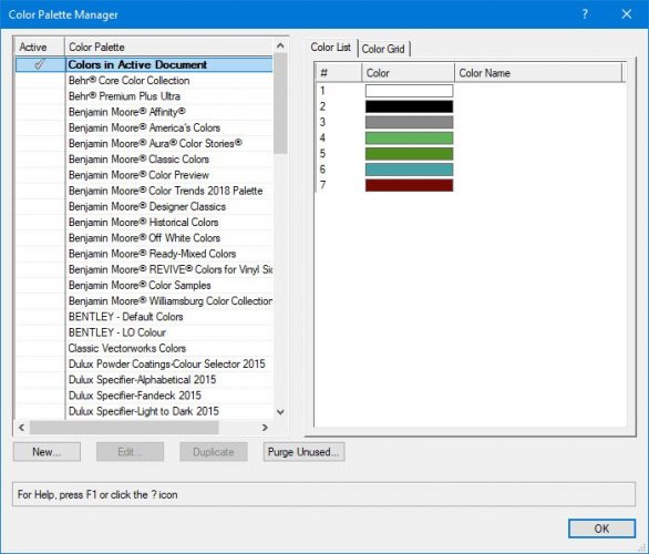
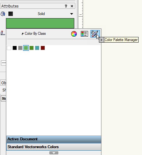
To purge unused colors, go to the "Attributes" panel and select the fill color

In the top right is the "Color Palett Manager", select this
Then on the LHS select "Colors in Active Document" the "Purge Unused" button at the bottom is now active, press and it will ask you to confirm you want to purge unused colors.
Hope this helps
-
1
-
-
You need to find the "Vectorworks 2020 Updater" application which is located in the application folder.
On windows this is located in: C:\Program Files\Vectorworks 2020\Vectorworks 2020 Updater\Vectorworks 2020 Updater.exe
Not sure what is the path on Mac.
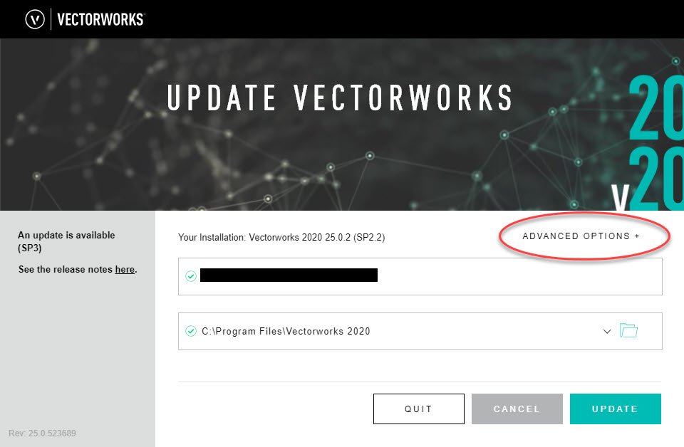
With Vectorworks closed start the "Vectorworks 2020 Updater.exe" you should be presented with the update window
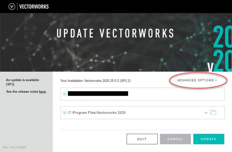
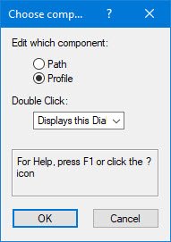
Circled in RED is the "Advance Options" drop down menu.On windows hold the ALT key and select the "Advance Options" drop down menu, you will now see an option to "Change Version"
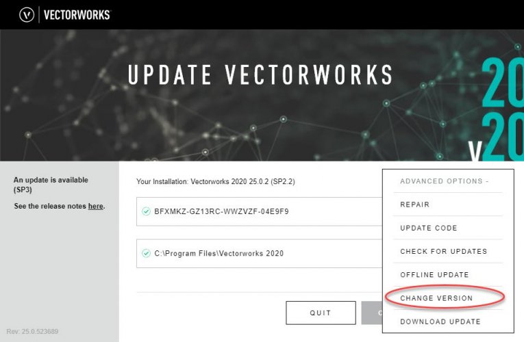
Select which version you want to change back to.
-
I can do in the morning as have finished for tge evening.
ps.
Regarding reverting back to previous version, i remembered how to do it, was getting frustrated trying to get work out.
Alan
-
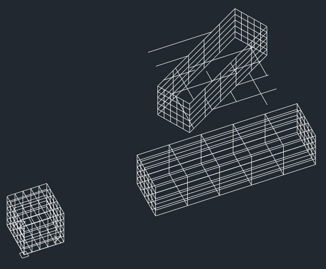
I have just updated VW2020 to SP3 and exported some file to DWG that I have been exporting earlier in the day, after export the DWG.
On opening the file in ProjeCAD (also checked in AutoCAD) the DWG is a mess with lines all over the place.
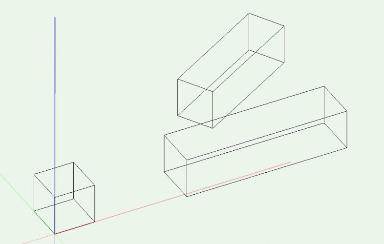
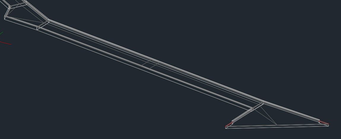
Extract of model below - Original exported prior to SP3:
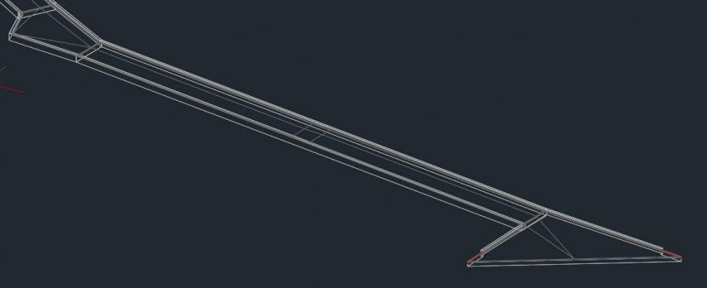
After updating to Sp3:
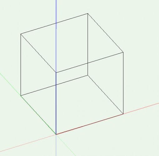
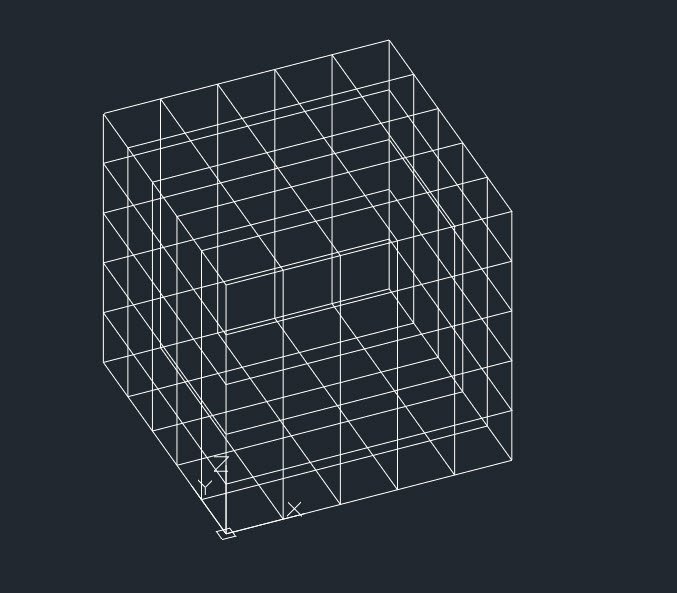
I have duplicated this in a test file by creating a extruded rectangle (5x5x5m) square to grid.
Exported to DWG using the same settings as previously used and opened in ProjeCAD
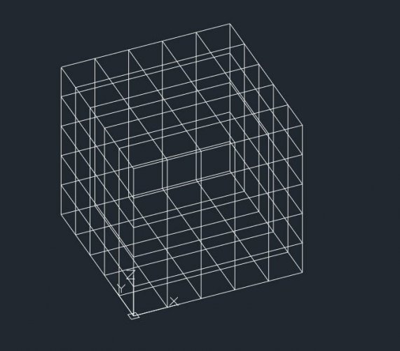
Each face is now subdivided.
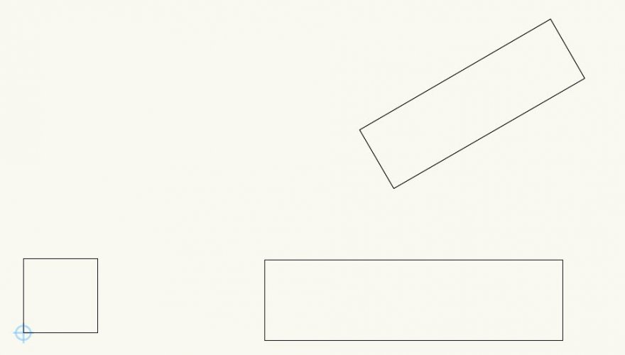
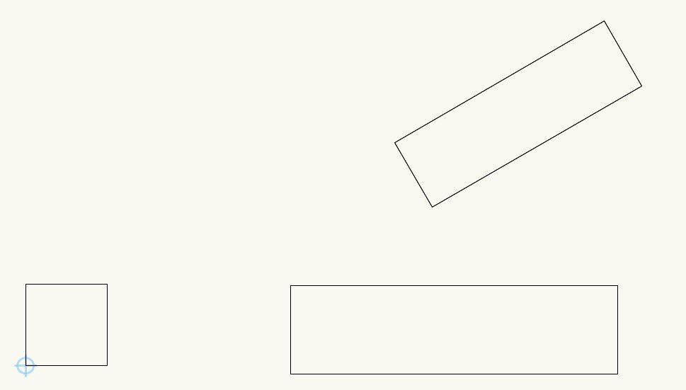
In the same file I then created two additional extruded rectangles, one square to the grid and one rotated.
Plan view:
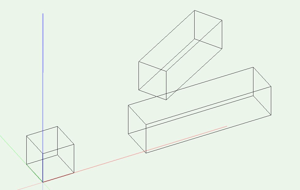
3D perspective View:
Again exported to DWG using the same settings as previously used and opened in ProjeCAD
3d Perspective view:
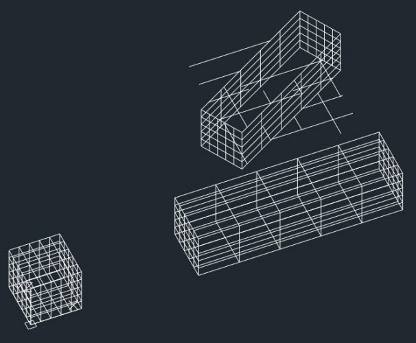
The top and bottom surfaces of the extruded rectangles that was rotated are now a mess.
The extruded rectangles that are square to the grid appear intact apart from each face now subdivided.
Can you please advise how to revert back to VW SP2 as I have wasted a few hours now messing around with this.
And fix this ASAP
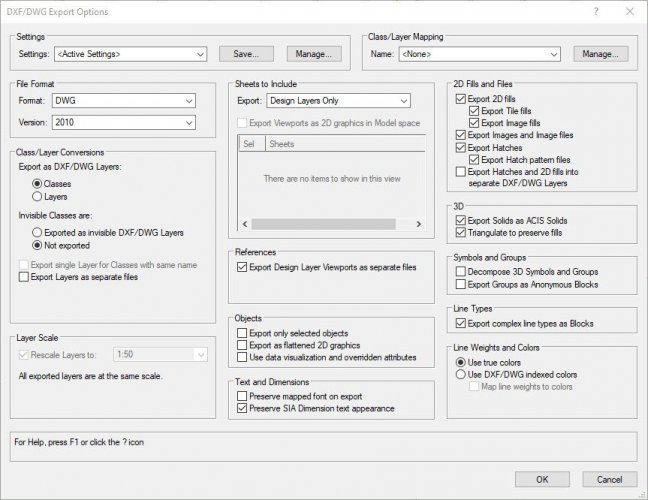
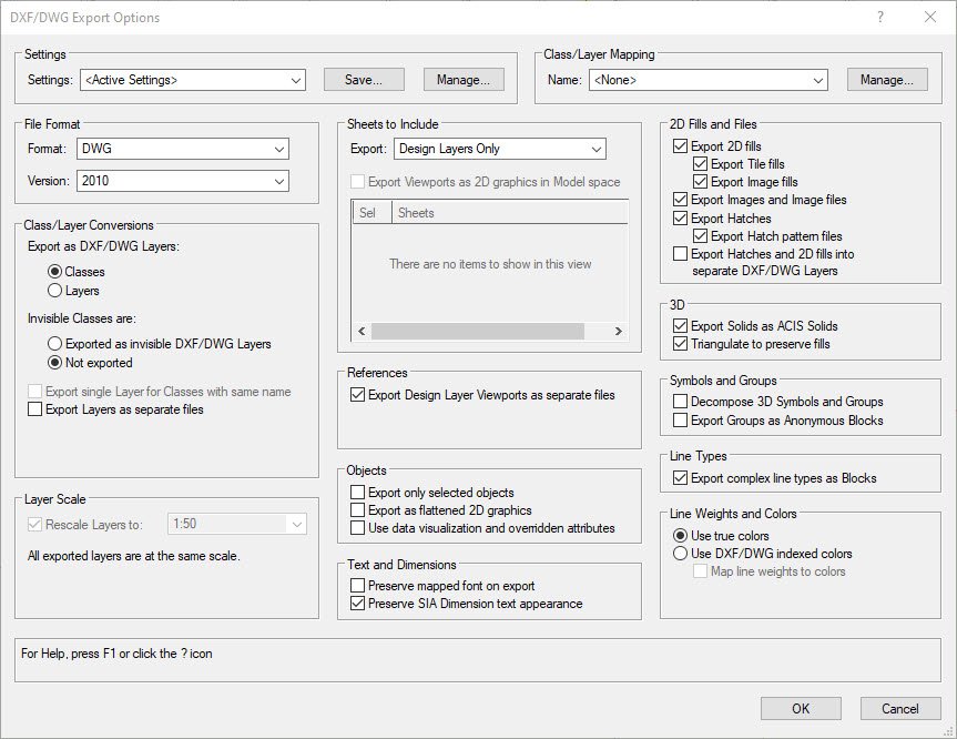
Setting as used in the export for reference:
(Have also tried changing the settings but same results.)
-
You don't have to do (step 4 & 5) I just like to keep things balanced when modelling and translating to different CAD systems it sometimes helps.
It will work once you have converted to NURBS.
Let us know how you get on.
Alan
-
2
-
-
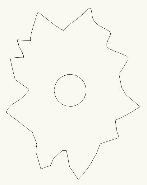
Extruding from an irregular shape such as what you have to a circle are beyond the limitations of Vectorworks and most CAD applications.
As a workaround:
1. In plan view; place a circle that will be the top in the desired position

2. Switch to a side or isometric view and elevate the circle to the desired height (vertically)

3. Convert both to NURBS ( Modify > Convert > Convert to NURBS )
Note: If you have selected both and then converted you will need to ungroup.
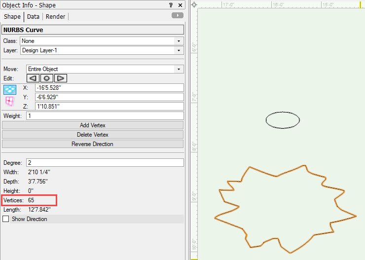
4. Select your tree (bottom shape) and look in the OIP
Check how many "Vertices" your shape has... 65

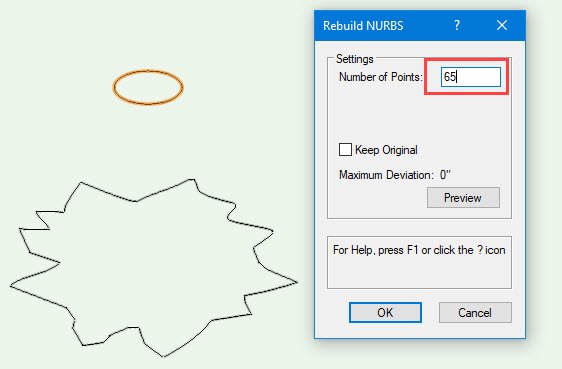
5. Now select the circle and... ( Modify > 3D Power Pack > Rebuild NURBS )
In the "Number of Points" enter the number of vertices that the lower shape has (65 from step 4 above)
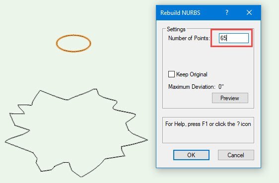
select OK.
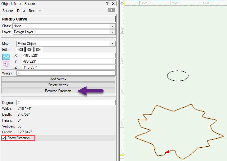
6. Select one of the shapes and in the OIP tick "Show Direction"

Check that both shapes are in the same direction; if they are different this wont work or you may end up with some twisted shape.
If they are in different directions select one of them and in the OIP select "Reverse Direction"
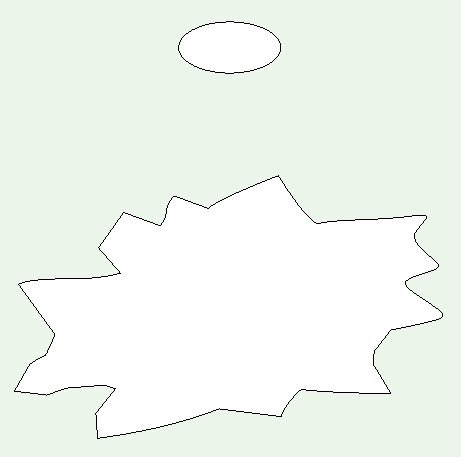
7. Switch to plan view as easier to select
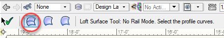
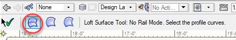
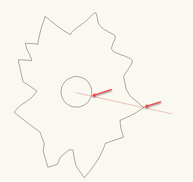
Select the "Loft Surface Tool" from the 3D Modelling toolset.
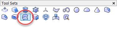
You want to select the 1st option "No Rails Mode"
Now select the lower shape first then the circle (as we converted this to NURBS with 65 vertices it is no longer a true circle which is what makes this work)
Try and pick the two shapes in line as shown in the image below (from a vertices to vertices )
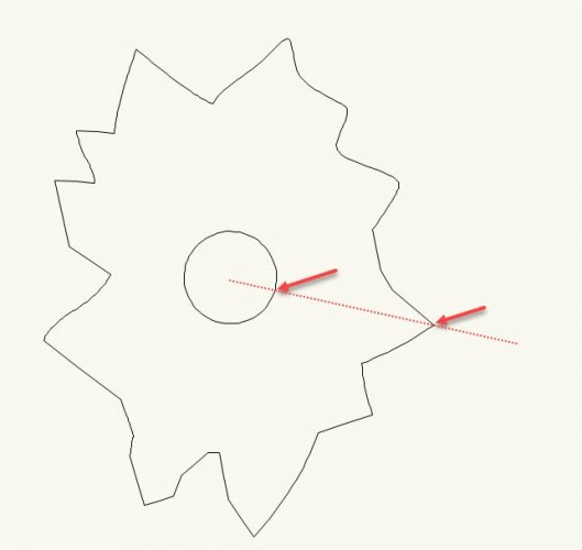
Select the "Green tick" to accept.
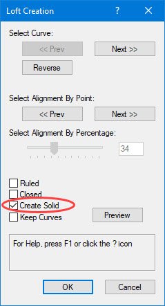
The "Loft Creation" panel is displayed, select "Create Solid" then OK
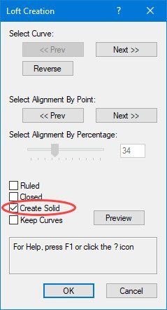
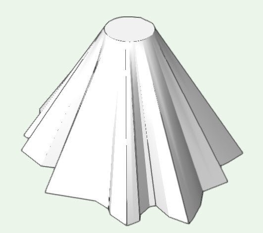
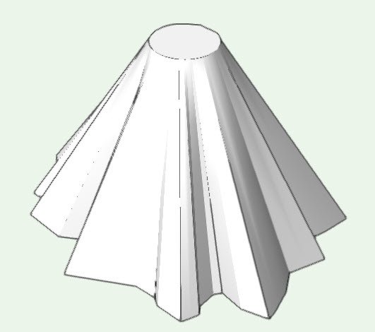
Switch to 3D view and you should have as close a possible to what you are trying to achieve.
Hope this helps
Alan
-
4
-
-
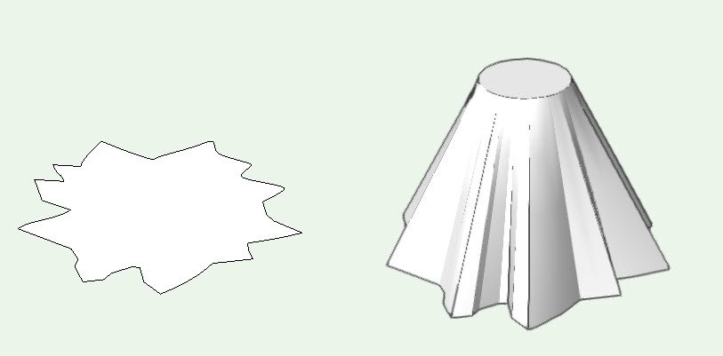
Is this what you are trying to achieve?

-
Thank you
-
1
-
-
I have received a point cloud file in .pts format and have imported this into Vectorworks 2020 Sp2.1.
I have played around with different combinations of settings but the imported point cloud is always coming in centered about 0,0.
As a check I have imported the same point cloud into Microstation and this aligns in the correct coordinated space.
Is there a trick I am missing or is there a problem with the import of point cloud data in to Vectorworks 2020
I've created an extract of some of the points for testing (first 3000 point) as the original file is large and takes considerable time to import.
Attached below for reference (had to zip the file as .pts file extension not acceptable to upload)
Extract - to world Coords.zipExtract - to world Coords.zip
-
Hi Tamsin,
It would be really useful for us end users to have some examples of how this works, there are many options to set within the “Document Georeferencing” panel as well at the options in the “User Origin” panel that are not clearly explained in the help file on what combinations work in what way and the lack of tutorials or videos which have been requested many times by users on the forum and the fact that users are still asking how to get this to work means it has not been clearly answered.
Could you please give us an example of where we have an existing file set up with the user origin set using X and Y coordinates and how we get this to align with GIS
-
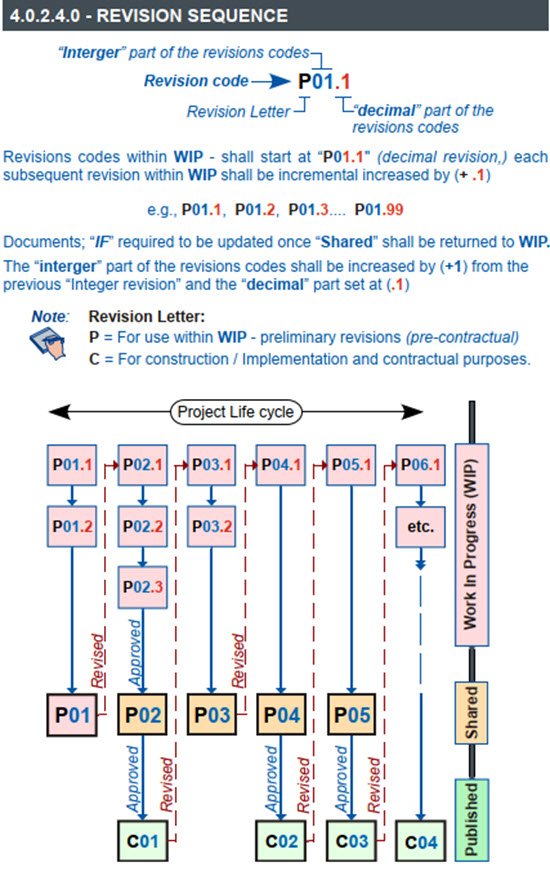
The issue process is long-winded but most of this would go on in the background of the EDMS, hopefully this will explain how the revision and suitability codes work.
Things to remember:
1st, the sequence of suitability codes is just a list, documents do not have to be issued in this sequence and not all codes will be applicable to any one project, some companies chose to only use a sub-set of these codes.
2nd, ISO 19650 assumed that a Electron Document Management System (EDMS) will be used to manage the Common Data Environment (CDE)
3rd, A document to be SHARED cannot have a decimal point revision.
Where a new document is initially created in the EDMS it would be assigned:
The revision code of: ( P01.00 ) and a suitability code of ( S0 )
The file has never been issued at this point; thus a (decimal revision of .00) and it’s suitability is Work-In-Progress (WIP)… ( S0 )
Example:
Two company’s (“A” and “B”) are working on the same project using something like drop box to share and are required to exchange information between them before delivering to the client.
Company “A”
Creates a new document named: Building Outline – P01.00_S0.vwx
The file has never been issued at this point; thus a (decimal revision of .00) and it’s suitability is Work-In-Progress (WIP)… ( S0 )
Company (A) has their first go at defining the building outline and position of doors and windows etc. Once done they save their file as: Building Outline – P01.01_S0.vwx
Company “A” now looks at their design and makes comments with other internal team members.
Company “A” now updates there design with the comment.
Once done they save their file as: Building Outline – P01.02_S0.vwx:
(at this point they can continue to progress their design)
Company (B) needs to get started on their Landscape design so need to see what Company (A) have defined as there Building Outline.
Company “A” gets to a point where it is happy to pass there initial design to Company “B”
To ensure Company “A” has traceability of their design the file needs to be SHARED.
(For a document to be share the decimal point revision need to be dropped.)
As this is the first time the document has been SHARED it will go out as revision: P01
Company “A” needs to select from the available suitability codes one that best fits the purpose for which they are sharing the file, at this stage ( S2 ) (for information) would be a good choice.
They save a copy of their file as: Building Outline – P01_S2.vwx This file is then issue to Company “B”
Once issued; Company “A” copies their file and updates the revision code to the next in sequence ( P02.01 ) and retune it to Work-In-Progress (WIP) … ( S0 )
The current file is now: Building Outline – P02.01_S0.vwx
Revision sequence:
Building Outline – P01.00_S0.vwx File created in WIP
Building Outline – P01.01_S0.vwx First save point in WIP
Building Outline – P01.02_S0.vwx Second save point in WIP
Building Outline – P01_S2.vwx SHARED (S2 for information)
Building Outline – P02.01_S0.vwx File returned to WIP
Company “B”
Company “B” received Company “A” file.
They create there own file: Landscaping – P01.00_S0.vwx
They reference Company “A” file in and add their information.
Once they have created there initial design outlines they need to pass there file back to Company “A” so they can see what they are proposing.
To ensure Company “A” has traceability of their design the file needs to be SHARED.
For a document to be share the decimal point revision need to be dropped.
As this is the first time the document has been shared it will go out as: ( P01 )
Company “A” needs to select from the available suitability codes one that best fits the purpose for which they are sharing the file, at this stage ( S2 ) (for information) would be a good choice at this stage.
The file would be issued as: Landscaping – P01_S2.vwx
Once issued; Company “B” copies their file and updates the revision code to the next in sequence ( P02.01 ) and retuned it to Work-In-Progress (WIP) … ( S0 )
They save the copy as: Landscaping – P02.01_S0.vwx
Revision sequence:
Landscaping – P01.00_S0.vwx File created in WIP
Landscaping – P01.01_S0.vwx First save point in WIP
Landscaping – P01_S2.vwx SHARED (S2 for information)
Landscaping – P02.01_S0.vwx File returned to WIP
Company “A”
Company “A” receives the file form Company “B” and can reference this into their file and see what Company “B” propose,
Company “A” updates the design within their file: ( Building Outline – P02.01_S0.vwx ) with some changes that affect the Landscaping so need to re-issue their updated file to Company “B”.
Company “A” saves a copy of their file as: Building Outline – P02_S0.vwx
And issues to Company “B”
Once issued; Company “A” copies their file and updates the revision code to the next in sequence ( P03.01 ) and retunes it to Work-In-Progress (WIP) … ( S0 ) so they can continue working on the design in their file.
They save the copy as: Building Outline – P03.01_S0.vwx
Revision sequence:
Building Outline – P01.00_S0.vwx File created in WIP
Building Outline – P01.01_S0.vwx First save point in WIP
Building Outline – P01.02_S0.vwx Second save point in WIP
Building Outline – P01_S2.vwx SHARED (S2 for information)
Building Outline – P02.01_S0.vwx File returned to WIP
Building Outline – P02_S2.vwx SHARED (S2 for information)
Building Outline – P03.01_S0.vwx File returned to WIP
Round and round the process goes… as the design progresses the suitability codes of the relevant issues will change and the revision numbers will increase.
Only when a document is issued for construction will the revision code change from “Pxx” to “Cxx”; Returning back to “Pxx” should any changes need to be done then re-issued as “Cxx” as needed, see below.

-
2
-
-
Sorry for the late reply was off sick last week and only now back on my feet.
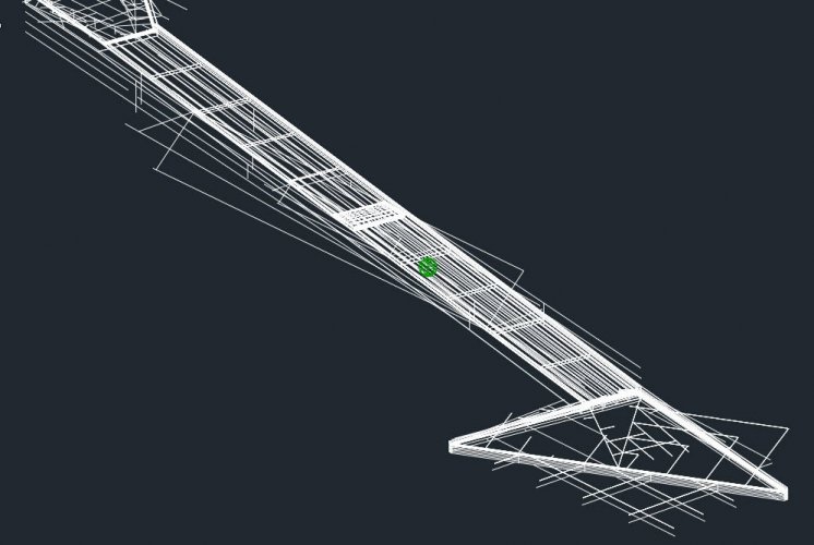
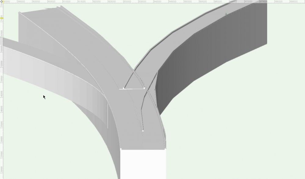
I found my notes from the work I was doing regarding a viaduct curve etc., the best results I obtained at the time I have translated into the workflow below relating to your original model.I have had to convert the model up to 2020 version as this is all I have on this workstation at the moment but workflow should work in previous versions without to much change.
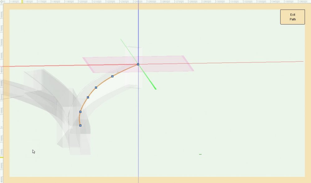
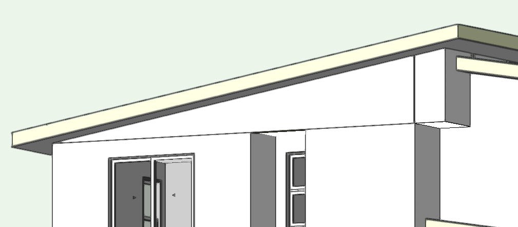
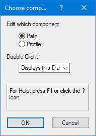
I selected the RHS branch from the screen shot below to apply the workflow,
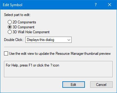
Double click to edit the symbol and select “3D Component” to edit
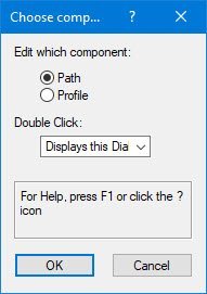
You will need to double click until you get the option to edit profile
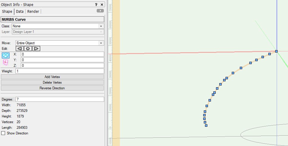
With the NURBS Curve selected; From the OIP we can see the “Degree” is set to 4
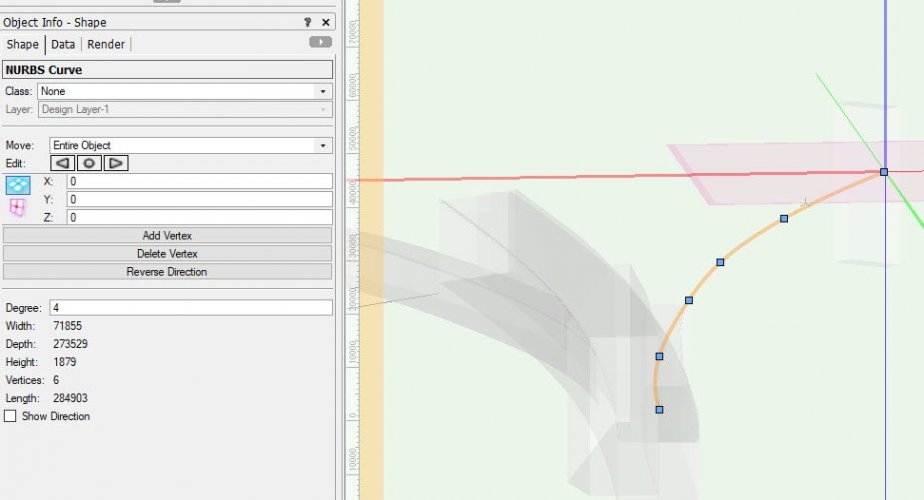
If we change the “Degree” to a higher number say: 7
Additional points are created (If you want you can change the Weight" value.... it doesn't do anything... but you've paid for it so you might as well give it a go, ha it might work one day)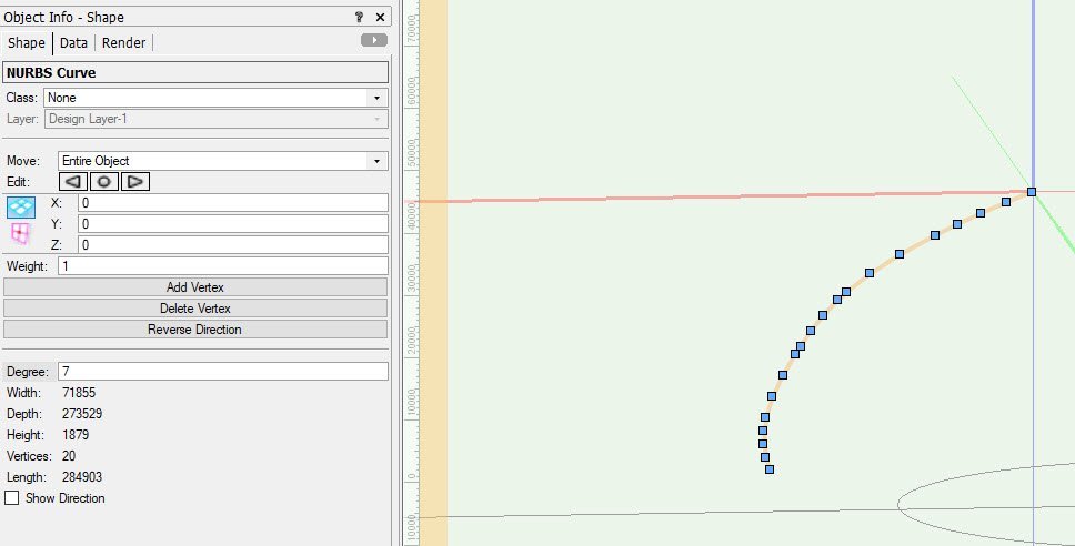
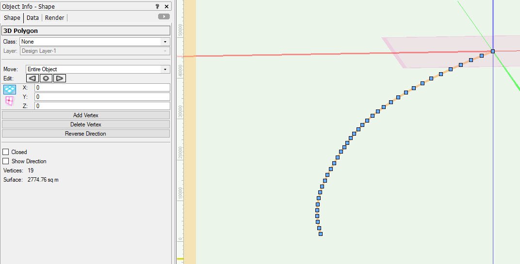
With the NURBS curve still selected now convert to a 3D Poly: Modify > Convert > Convert to 3D Polys
The additional points are added and distributes more evenly along the curve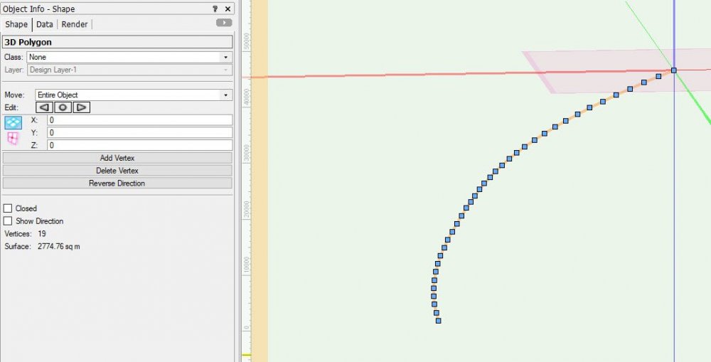
Exit the path
Double click on the object and now edit the “Profile”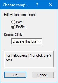
With the profile selected also convert this to a 3D Poly: Modify > Convert > Convert to 3D Polys
Now exit out and check the results
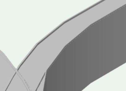
Original: Converted:


It’s the best your going to get from VW 😞
Visually smother but due to the conversion and issues with NURBS curves etc., only the start and end points pass through the original points, all other points have moved off of their original line -
No, raised it as a potential but but never heard back from anyone.
Agreed; In you screen shot above the orange line shows the true geometry of the curve but the VGM is simplifying the curve by faceting it.
Had a similar problem many years ago with Bentley MX Rail, doing rail alignment, all curves were displayed as faceted, took several weeks for someone to find out there was a check box within the application to enable curve fitting which once checked produced nice smooth curves, unfortunately it doesn't look like Vectorworks has this capability.But as I found without having a curve pass through the points as intended you will always end up with something that is an approximation and not what I needed to work with other design teams, when I passed some sections over to them they did not match the sections they created, slightly out each time due to the faceting problem.
-
1
-
-
I did some time ago do a comparison of the lack of accuracy relating to the faceting problem with curves, I compared the results from Vectorwork, AutoCAD, ArchiCAD and Microstation and found the results interesting which does pose a problem when trying to work with others
-
Yep, went through the same process but gave up as results were not good, after several days of trying splashed out £200 and bought ProgeCAD, took about 10 minutes to do it and import in to Vectorworks.
The amount of time I spent trying to get a smooth result out weighed the cost of something that worked.


Gap in Wall fit to object
in Architecture
Posted · Edited by axhake
Your welcome, you may also consider purging your file as there were a number of unused elements that can be removed to clean the file and reduce its suze.