
Elite Exhibits
-
Posts
588 -
Joined
-
Last visited
Content Type
Profiles
Forums
Events
Articles
Marionette
Store
Posts posted by Elite Exhibits
-
-
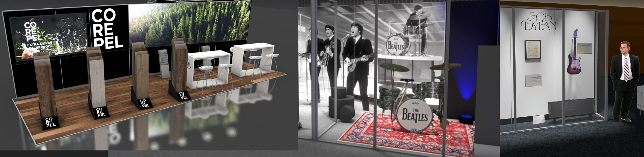
On a similar note … In a perspective view, should one be able to duplicate and manually move a symbol, or even a simple extrude, and have it remain on the Active Layer Plane?
As an example, (see attached) when I place a 3D Symbol, in a perspective view, it appears to "float" across the floor (i.e.: the Active Layer Plane) maintaining perspective, until I double click. After this symbol is placed, manually moving it, does NOT keep it " on the Active Layer Plane". Holding the shift key restrains it in one direction, but not the others. - Still Puzzled - Peter
-
Or should I say excellent - Peter
-
Tim, excellant - thanks for the help - Peter
-
Nic … what specifics did you use to create the illuminated version of the SPAR sign … looks great! Peter
-
Although I have used VW / RW since MiniCad, recent "enhancement" features have caused additional steps to be required. Some where there were none needed in the past. I experience this when I cut and paste in place and get a result that is not as expected. (Please see the attachment) I assume I am not in control of the Working Plane(s)?
1. Original item was a Group with a Hybrid Symbol inside.
2. Part of the group should have been an integral part of the Symbol.
3. As drawn, it was in the correct XYZ position (a pair of oval feet) (1)
4. Top / Plan View
5. Select and Edit the group,
6. Select the two "Ovals" and cut.
7. Select and Edit the Symbol
(The Symbol remains it the exact same position and orientation)
8. Paste in place …
9. Ovals are now off to one side. Not as expected with paste in place. (2)
10. Undo
11. Select the top center of the Symbol with the cursor "click"
12. Paste
13. Ovals are now positioned as expected.
14. Exit Symbol
15. Select Saved Perspective View
16. Check that … Oval are now half way up the side (Z) from where they should be. (3)
17. Edit Symbol
18. Front View
19. Select Ovals
20. Manually move ovals down into original position.
21. Exit Symbol
22. Allset
Questions:
A. Should "Paste in Place" work in all three directions as I feel it should ?
B. Is there a way to "lock" the working plan to the ground plane, even if you switch to a front or side view?
C. Is there a way to have 3D symbols stay on the ground plane, or move automatically down to the ground plane? (i.e.: Gravity?)
Suggestions on what to do different ?
Thanks in advance
Peter
MacBook Pro Retina
OSX 10.8.5
VW / RW 2013 P5 (Build 208827)
-
My 2¢ - None Class is always on … Top / Plan (Keyboard Shortcut "5") is what we use for a "default view".
We use Saved Views that ... only remember Class Settings, … are saved inside of a Symbol or Group Edit, … are temporary (Dummy Saved View), … jump to a desired view, without the current Class set up changing. …only change the RenderWorks settings for a quick rendered view.
Recent job that went to Hamburg, had almost 75 Saved Views - A portion of these were to show the client what they would see in the finished state and some were the "Same View" with limited Textures to highlight specifics for the crew that would do the assembly. - Peter
How do others manage this scenario? … there seems to be no way to "exit" a saved view, I'm thinking that one possible solutuion could involve creating a "Dummy" Saved view which has a set of visibilities applied to it so that a "default" view can returned to.
-
As the cost is not a small one, has anyone utilizing VectorWorks, subscribed to http://www.lynda.com and found it worth the cost ? - Thanks ...Peter
-
Example of Symbol count - Peter
-
On the same subject ... has the search in VW Help been "fixed" ? - Peter
-
Easiest method to "Count" anything is to make every item that you want to appear on an inventory list as a Symbol. Even if there is a single instance of that item.
Name the Symbols logically, so that the items appear (alpha - numerical) together in the Worksheet, if you want to count them together. ie: Deck Section 96x48 black, Deck Section 96x24 black etc
The Worksheet will list all the Symbols. The "summation" option will then group identical instances together. I will post a ready made Worksheet that counts symbols. Peter
-
It is ironic that some items can be created from the center and reshaped from the center ... Circle, Rectangle, while a Line can be created from the center, just not reshaped from the center ... with the cursor that is.
The circle is a given based on its geometry. The Rectangle resizes from the center if the command key is held. This would be great if it served the same "resize from center" function on any shape.(See Claris CAD 1994) If the Rectangle is actually a Polygon of the same exact shape, the reshape from center does not work.
The Fixed Point resize tool, however, offers some options. For the "rectangular" Polygon, it will reshape from center after you identify the center. ie:locating the intersection of the appropriate mid points. Finding the center of a "rectangular" Polygon is often an impossible process. Workaround: Cut and paste, onto another object, one with a known midpoint. Use that midpoint as a reference with the Fixed Point resize tool.
For a Line, the Fixed Point resize tool "gets stupid". It will resize the line from center, only if the line is other than vertical or horizontal. Really not sure why this is ... Peter
-
Excellant - Thanks - Peter
-
Would like to make a custom HDRI Background of a specific venue
What software is needed for this ? Photoshop or ? - Thanks Peter
-
Would like to make a custom HDRI Background of a specific venue
What software is needed for this ? Photoshop or ? - Thanks Peter
-
This sounds good … (did not know it was as extensive) … Peter
-
We continue to have issues with Classes when an item (Typically a symbol) is copied pasted into a different drawing. The object looks 100% visible, yet problematic when an attempt is made to select it. Some classes appear to be on but they are not. Solution is to turn all the classes on. - Peter
-
Would it not be easier to simply make a "Decal" in the traditional way? Create a texture with a transparent mask and apply it to a thin shape. - Peter
(Page one is the New Decal (thru and out the back) - Page two is the traditional method front only)
-
If you watch the Knowledgebase Video on Auto Hybrids you see what (we assume …) VW wants you to use them for. We have found, that Auto Hybrids can have a visual size, and then an assumed size. (Top Plan View) If you click on a corner, as you see that it is the corner of the object, it may NOT select it as expected. If you select the Auto Hybrid and zoom out. With "Select Handles" on, you see a different location for the bounding geometry. Often some or all of these "point" is out in space. This may be more evident when the Auto Hybrid has been moved or rotated.
With strange geometry the Auto Hybrid has some logic, with simple geometry, it appears to have "issues". - Peter
-
Great idea! " ...it would be great if you could 'Send to surface" a vehicle and it would position itself based on the current model."
I found my first request to VW Tech Support for info on how to use the "Send to Surface" outside of the DTM world. Its dated 7/26/05 … Never got it to do what I wished it would do. Essentially act as Gravity.
Peter
-
While we are on the subject … there are several tools or menu items that we are frustrated with for the same reason. "I pretty much never want to use …"
In past history, there was an application called Claris CAD. If memory serves me well, one could select settings with the "Option" key, and that became the default.
As it stands there are some things that require several "clicks" every time as the settings are what "I pretty much never want to use …"
Peter
-
re: Automated Working Plane to match working view
If memory serves me well (in past VW releases) when switching to a different view VW did not leave the working plane "behind". Typically we do NOT use the working plane in any special way.
Work flow example: Place legacy 3D / 2D Hybrid Symbols in the Top / Plan view, arrange and group as needed. Switch to standard Front or Right Ortho Views to add or edit an item.
Example: Draw a 2D (Screen) Rectangle. Snap to one Symbol or group, snaps work as set. Attempt to snap to another symbol. Unable to select some (desired) points? Stop.
Pick Menu item, Modify / Working Plane / Align Working Plane with Current View. Start the drawing process again. Snaps work as expected. (Layer Option is set to "Screen Only"
It appears in this sequence that the working plane remains in the original Top / Plan View (Was this also a feature in the past?) The indicator is the fact that the the snaps do not work as expected in a Front Ortho View.
VW / RW 2013 Designer
MacBook Pro Retina
OSX 10.8.5
-
Where is there Help Information on Automatic Working planes ?
-
Light Tool - Spot Light Mode Icons … size, selecting, altering, issues
We tend to use a number of Spot Lights in our rendered drawings. The Icon that represents this Spot Light can have different characteristics. Most are helpful. The color of the arrow head or the spread of the reflector are indicative of the settings in the OIP.
Others, like the "Long Directional Arrow" that points towards the direction of the spot appear to have little to do with the fall off as one might expect. (Based on the Spread and Beam Dialog Box)
Question 1: Is there a way to eliminate that "Long Directional Arrow" after the Spot Light is placed?
The selection process is altered when a Spot Light has a that "Long Directional Arrow" in its icon. Both ends of the spectrum: "way to easy to accidentally select a light unintendedly" and the "way to hard to select with the rectangle marquee as the icon is bigger than expected.
On that note -
Question 2: Why are the Icons Gigantic is some views for the Spot Light (Perspective) ? They are 3D ?
Question 3: When a Spot Light is in a Symbol, the selected boundary is determined by the Spot Light ( … and that "Long Directional Arrow") even when the Preferences are set to NOT visible. Can this be altered at all? (Or is it … back to Question 1)
Question 4: When a Spot Light is created with the Dialog box it is easy to alter the settings put a Spot Light where and how one would like. A second time and some of the settings in the Create Spot Light Dialog box reset, others do not - Why?
Question 5: Is there a Way to select an existing Spot Light and tell it to focus at the "next click" ? (The way an Animation View can be told to "look at")
Thanks ...
VW / RW Designer 2013 SP5
MacBook Retina 10.8.5
-
In general I found that the send to surface only worked for a limited range of things in specific conditions. As you have noted "flat onto flat" is a key. It is NOT "gravity" as one may expect. I gave up on it years ago. - Peter
Alt/Option Modifier While Resizing
in Wishlist - Feature and Content Requests
Posted
I use the Fixed Point Resize Tool to reshape some objects. A rectangle from the center for example. It has a failing or two. If a Line, for example, one that was drawn from the center, is to be reshaped, from the center, it must be at an angle other than Zero or 90. Any angle, just not Zero or 90.
Try it.
1. Draw a line, from the center, with an Angle of Zero.
2. Fixed Point Resize Tool.
3. Select the center of the line.
4. Attempt to manually reshape the line from an end point.
5. Fixed Point Resize Tool Fails.
6. Rotate the line with the most minute fraction of a degree
7. Fixed Point Resize Tool
8. Select the center of the line
9. Fixed Point Resize Tool works as expected, resizing the line from the center.
Point is ?
I have used the Fixed Point Resize Tool to resize some strange 2D shapes and groups "from the center", selecting a corner of the "bounding box". Problem is selecting the center of the "bounding box".
Not sure this is a solution to what Kevin is looking for. - Peter