


scottmoore
-
Posts
673 -
Joined
-
Last visited
Content Type
Profiles
Forums
Events
Articles
Marionette
Store
Posts posted by scottmoore
-
-
I would not bring in a venue DWG file into my working file. I always import into a blank file and then spend as much time as I can afford to clean it up. Then I just viewport that drawing (as Pat mentioned a “shuttle file”) into my project file.
-
Mark’s suggestion for creating a “red symbol” will give you what you are looking for. You can add a label legend as well prior to creation.
-
 1
1
-
-
By the way, I would imagine the reason to have the "types of lights" embedded classes would have been more about adding color coding to those types of lights probably based on the preference of a certain shop. The real issue with the embedded classes was not having a strict naming convention in place prior to development. A simple number or letter could have solved a lot of the mess.
-
And one other related issue; occasionally I’ll have an image based texture with a reflection added. The issue would be the image disappears and the reflection stays. For instance, instead of a nice glossy wood floor, you have a really bright white floor with a sheet of ice on it.
Any suggestions?
-
Any time you add indirect lighting and high quality anti-aliasing, your render times will be impacted somewhat drastically. I would suggest spending 30 minutes or so experimenting with glow textures. They only emit light if there is another light source in your drawing (VWX does not recognize a glow texture as a light source and as such, the general ambient light from over your left shoulder cannot be turned off) and it requires indirect lighting to really see it. The results can be really great however.
-
Greetings. I’ve been running into issues with textures created with images. I typically use a lot of these in my work. For some reason, when rendering on the design layer, certain of these textures will disappear. It often happens every time I render. The solution seems to be to select edit for the texture specific texture to open the edit dialogue box, and then close it while doing no actual editing.
this seems to rectify itself once I use a RenderWorks camera to create a viewport on a sheet layer for exporting. I have closed and reopened files in question, restarted VW, and restarted the computer to no avail. Unfortunately, it is a huge waste of time in the design process. Has anyone else seen something like this?
-
Another approach might be to create a linear piece of geometry and apply a glow texture. You would have to render with indirect lighting enabled, but you can create some really smooth linear lighting. It often takes a really high output on the glow texture (sometimes as high as 1000+%) but the results can be pretty great.
-
1
-
-
AMEN MARK!
Your comment on Saved Views is spot on as well. Arguably the most overlooked powerful asset of VWX.
One other suggestion for those struggling with the class parade: If you want to keep the existing VWX embedded classes and still create a template file (you should absolutely create a template file), add some class tags to the autogenerated classes and your specific drawing classes (flown, floor, house, booms, whatever you might call your classes) then add a class filter to select that particular tag. When you select that filter, all you will see in your nav palette are the classes specifically associated with your lighting fixtures.
For me, I've always used my own custom symbols and have a template set-up to accommodate them. On occasion I have to share my file with other designers and then comes the class parade and none of my saved views, sheet layer viewports, etc. work correctly. My solution in my updated template was to include all the lighting and BraceWorks classes in my template as well and include all of that information in my saved views and sheet layer viewports. When I run my LX filter, it brings up all of the associated lighting classes, including my drawing classes, my custom embedded classes and the Spotlight classes. Now I don't have to be quite as frustrated as I was as it doesn't matter if I amusing my symbols or someone else's inserted symbols from the VWX libraries. The drawing still works the same.
-
1
-
-
Those embedded classes do serve very necessary purposes even though my opinion is some of the lighting symbol classes are just not necessary. A good way to wrap your brain around the purposes of embedded classes would be installing a BraceWorks truss. The embedded classes allow the end user to choose between simple and complex truss options and other items. Again, the class naming is a little odd (having a class that uses the word “truss” then a hyphen and then “truss” is kind of like including the word being defined in it’s own definition).
The separate class for a lens would be ideal so that not only could you use a lens with a glow texture, but it could also change color appropriately simply changing the “color” field in the OIP or edit fixture window.
My personal opinion is that embedded classes should ONLY be used to control the attributes of a symbol selection; what parts are visible, co trolling line weights, pen color, fills, etc. This functionality is spectacular. It should never have been used as a way to categorize symbols. That is the designer or drafter’s job. Again, in my opinion, the “wash”, “incandescent”, “moving light” etc. classes are completely superfluous and serve no viable purpose, especially now that your profile lights and wash lights might very well utilize LED engines.
rant over.
-
1
-
-
I just ran into this as well. I had my scene set up, with 11 fixtures using gobos. Adjusted light levels, changed colors, moved focus points, all with no issue at all. I made one last color change to five of the lights and now no gobos at all. I've removed the gobos, re-imported them, selected different gobos, refreshed fixtures (selected and globally), restarted the file. Still no gobos. Of course, I am on a deadline. (hard to believe in our current pandemic shut-down)
-
I'll jump in on the requests since this started with a question I have for Andy. I was not having much luck making this work and would be fine even if I had to have a DV for each type of hoist. ....and Pat beat me to it.
-
Lighting instruments, like many other symbols, included embedded classes for control purposes. The easiest way to wrap one’s head around this is to drop in a lighting symbol in a blank document. You will see the specific classes created. The symbol itself can be placed on a class of your choosing. To view it, your custom class must be visible, however, some or all elements of the embedded classes must also be visible. By using this method, you can decide if you want to see the movement radius, the “whip” location, etc. it’s actually pretty useful but I would add that the existing class scheme is dated and a bit of a mess. It’s the kind of thing that starts out as a simple idea and then gets added to, and mucked about with over time so it is what it is. It would take quite a lot for the VW team to change it at this point.
One solution would be to create a library file of every fixture you might ever intend to use and, once all the symbols are imported, you can change the embedded class names. I believe there may be some class mapping options now available for this purpose, but if they exist, I’ve not used them.
-
1
-
-
All the above suggestions will work and are spot on. A transparency in front of your LED display will work but I find that I spend quite a bit of time making it look as it should, especially if I am adding a touch of reflection to the plastic. If you don’t need that level of detail, it would be much quicker to blur the image in advance and you can add some reflection to the glow as well.
-
I am liking this feature a lot! I think it will be a great time saver and error check.
-
1 hour ago, markdd said:
There's a really annoying bug in 2020 at the moment where symbols leave a shadow or remnant of themselves on the design layer without actually being present. A simple Save and Revert to save command solves it in my experience. It's been around since the introduction of 2020 and I wish the engineers would fix it.
It’s exceptionally annoying and surprisingly frequent. I “think” it happens when you insert the first instance of a given symbol but not entirely sure.
-
On 4/26/2020 at 7:33 PM, Carla Rose said:
Hi Wes,
I have taken your advice here and cerated a texture from an appropriate herringbone tile image. Although now I have a think line between each segment of the texture. I have played around for a while and can't find a way to remove that border/line. Any advice?
Thank you!
You may have to manipulate the crop of the screenshot to make this work. Also, you can draw just about anything you might want in VWX (it’s vector drawing by default), screen grab it and create textures from it. I do this ALL the time. In this case it is just about creating a seamless texture.
-
1
-
-
The Savvy plug ins are indeed very slick!
-
2
-
-
Carla,
for this sort of thing you would want to find a “seamless” texture. Note that many free textures online that include the name “seamless” actually are not. Ensuring that the image is properly cropped will be important as well. Unnecessary for images that are truly seamless.
-
There are some rendering bugs in VWX no doubt. I typically only see them in design layer rendering. Often the suggestion is to render in sheet layers but that is completely impractical in most people’s workflow. I am constantly rendering in OpenGL, Custom Renderworks, Hidden Line and occasionally even Final Quality while modeling on the design layer. That is how I go about determining progress in modeling, texturing and lighting. Here are some issues I see on the design layer:
- once a view is rendered in one format, it often will not render in another until you change views
- textures the might work fine in OpenGL (including an OpenGL Preview of a RenderWorks render) will simply disappear in Renderworks. This seems most prevalent when using image textures that receive color filtering by object.
- editing textures can sometimes cause other textures to disappear or even the entire drawing disappear in RW
- often textures, specifically those that are image based shaders with reflections, can lose their image leaving only the reflection. The solution seems to be to open the texture (edit), do nothing and then close it.
And yes, the status bar is only marginally helpful.
-
1
-
-
Glad to help.
-
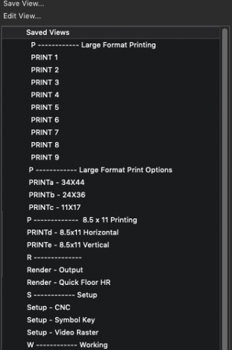
I will say this: do NOT overlook "SAVED VIEWS". I get files from people all the time and seldom see anything with saved views. Part of the issue is the name. I think most people seem to think it is just for saving "views" and assume they already have quick access to plan, isometrics, front, back, sides, etc. It's FAR more powerful than that. It would probably be better termed SAVED STATES". Here are some things for which it can be useful:
Navigating towards various sheet layer print set-ups.
Navigating to your camera views for renderings if you use those
Navigating to a set-up layer if you use those
---All of the above can also be done from various other navigation locations, however, once you get in the habit of going to one location for all navigation, you will find this speeds up workflow quite a bit.
Save a few 3D views with no classes or layers saved so you can do quick views of your modeling in 3D, regardless of what classes and layers you have active while in the design process.
Save any number of set-ups with classes and layers visible, greyed or off. Class and Layer viewing options can be saved as well.
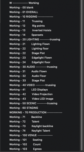
What I call "Working" views. These are views that are set-up specifically for what I am working on at the time. If I am laying out flown lighting, I go to that saved view and it turns on or off whatever I would normally need to see, and makes the correct layer and class active so any fixture I import into the drawing automatically goes to the correct class. Same is true for any department or sub department. Once you get the hang of working this way, you will be shocked that you ever did anything else.
I am attaching a couple of screen shots of my saved views. Note that I work in a lot of different settings and have to be able to accommodate any number of departments and scenarios. Therefore I have a ton of classes, and saved views that will probably not be needed for every project. Also, I save a lot of blank views (the ones with the dashes) to help work as breaks so I can find things quickly.
-
4
-
-
22 hours ago, trashcan said:
I'd love to see counts work for other type of "Count" devices - like Speakers, Projectors. Seems like an obvious need to me.
That is done using “reports”.
Thing 1: make sure you are using classes (or layers) to organize your drawing
- Create Report (You can title it here or later)
- select Advanced Criteria (edit criteria)
- in the first drop down select “type”, in the second “is”, and the third “Symbol”
- select “more choices”
- select “class”, “is”, “whatever class you need”
you can add as many pertinent classes as you want. “Including components of:” will probably be set to symbols and possibly Plug-in objects depending on your usage.
select from: “Functions”
then add “count” and “SymbolName” to your report columns. Also select “Summarize items with the same “SymbolName”
That creates a report. You can make modifications to its appearance and formatting. You can close it out.
in your Resource Browser will now be a worksheet Instance. Double click on it and it will show up on your desktop.
My usage of these is to have my various worksheets pre set on my template file. They reside on a designated layer that holds iterations of any worksheets I need and my symbol summary. I then have viewports preset that populate the necessary item to their associated sheet layers. It pretty much automated the entire process short of recalculating the items (which you do by right clicking in this case)
Hope this helps.
-
4
-
-
This may not help you but is still a pretty cool hack. Set a focus point that is perhaps 20’ high and set it 1,000’ downstage its so. Call it “audience”, “straight out”, “house” or something suitable. Then you can select all of those fixtures and focus them to that point. With something like Magic Panels, there will be some pan as well which may not be the look you want but it’s still pretty cool.
Two additional notes:
1- I would make the geometry for this focus point much larger so you don’t get really confused when you perform a “select all” function.
2- you can duplicate this focus and send one duplicate way higher to create a quick arial focus and one duplicate way lower to create a “straight apron” focus. Both of these can be very useful for concert lighting and makes for a very expedient process. Keep those three focuses in your template file.
-
1
-
-
Thanks Pat. I should have clarified further.


Editing a 3D symbol
in Entertainment
Posted
Sometime back, there was a change in the way one edits a 3D symbol. I often find myself wanting to edit 3D symbols and typically this involves using some 2D geometry to create new or modified extrudes or simply drawing lines for registration purposes. The relatively new development (seems like the past two or three versions) is that any 2D elements immediately move to the 2D component of the symbol unless you change your 2D drafting plane to "symbol definition" or (I think) "screen plane". I would really like for the default for my symbol editing to be "symbol definition" as there are next to no instances where I would ever, while editing the 3D portion of a symbol, draw 2D geometry that I wanted to immediately disappear to the 2D portion of the symbol. Every time this happens it is "undo", set the plane to "symbol definition" and start over. If I do not utilize "undo" I'll end up with an errant piece of geometry in the 2D portion. Is there a preference specifically for this?