Hi - I am looking some help to place custom data tags at the upper and lower edges of sloped exterior steps and landings.
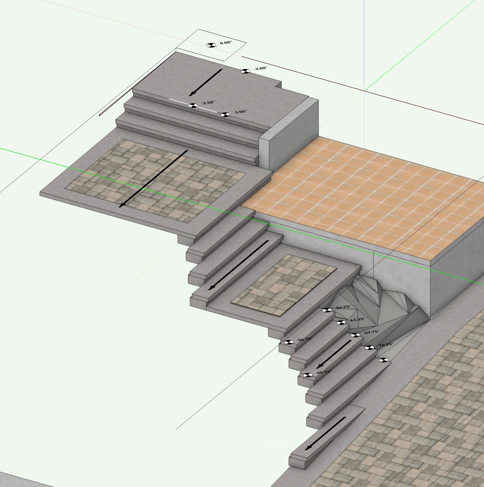
I do not have the Landmark package - perhaps there are automated exterior stair options for sloping treads and landings for drainage ? I have tried creating individual sloping hardscapes and individual slabs (with drainage) to build these steps - shown below are mostly push-pulled extrusions that follow the grade. This would be easy if the stairs weren't pitched - however they are and the lengths are staggered with the fall of grade
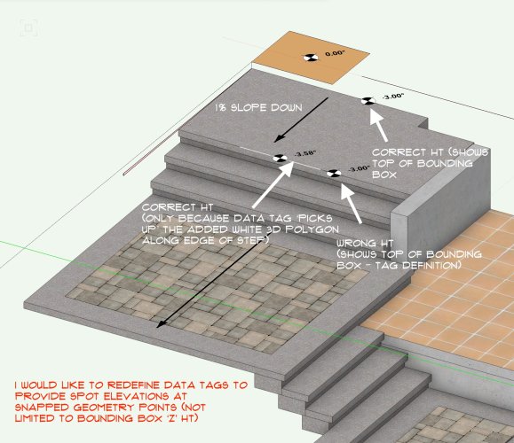
The problem I am facing is that the tags are set to report on the bounding box (#ZTBBG##in_2_1#) and therefore not providing accurate information as to the actual height of the objects lower edges when the tag is positioned there.
I am using auto-plane highlighting and locking to snapable points of the object - so the tags appear in the correct location visually but are not reporting the actual info of where they have been located when not aligned with the top edge (ie top of bounding box).
I understand this is because of the way the Dynamic Text is programmed, but unsure how to redefine the data tag field to achieve the correct spot elevation when snapped to these various slightly lowered edges.
The workaround shown below works by snapping a data tag to a white line (3d polygon) drawn along the lower edge of top landing. These extra snapping lines could be hidden in another class but seems to be an inelegant solution to do for each step. Can anyone suggest a proper data tag definition instead that will provide the correct distance below my established 0.00" at various snappable points inside the bounding boxes of a sloped/tilted objects ?
It would seem to be useful in other similar circumstances as well ...
Thanks in advance for ideas on this - probably an obvious answer but I've not found a way yet ... and not very experienced with data tagging TBH