


elc
-
Posts
138 -
Joined
-
Last visited
Content Type
Profiles
Forums
Events
Articles
Marionette
Store
Everything posted by elc
-
It does, thank you @Conrad Preen
-
ah, I see. but "customize" only means that I can pick one of 4 options, but exept for the arrow none of those options was suitable for my purposes. thought you meant I could fully customize the symbol itself (a star instead of an arrow). 🙂
-
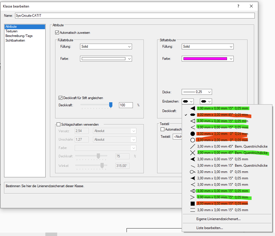
Thanks @Nikolay Zhelyazkov But I can change the markers to the ones highlighted in green in my screenshot? (Just not all of them. e.g. the red ones) Or am I missing the point? how would that work? How would I customize them? Couldn't find any arrow graphics as symbols in the library (under zNestedSymbols).
-
I might have overlooked a setting somewhere, but when I update a worksheet and export it to an existing Excel file it does not just overwrite the file, but first deletes it and then re-writes it. There is probably a good reason for this behaviour, but version history of a file is not possible this way. Is this a bug or a necessary feature... and could this be ajusted to at least give us the option in the settings dialogue to just do a normal overwrite?
-
I would like to have different symbols for different types of signals (arrow for unidirectional, diamond for I/O connections). And maybe even depending on wether the "jump" leaves the room or not. Is there a reason why I can't use all available symbols?
-
still didnt have time to create a file showing this issue. but it looks like I am not alone in this. 😉 ...
-
sorry, another bug I wanted to ask about: I don't have admin privileges on my CAD machine and I can edit all ConnectCAD settings except for the numbering systems. Everytime I exit the settings dialogue an error message appears warning me, that the changes to the numbering system weren't saved. Tested it with admin privileges and it worked fine. But as I said I usually don't have those. Company policy. Asking our administrator every time I want to make a change is not really an option. It's already strange to require admin privileges for an VW update, but I can live with that. But setting changes within the software should be available to everybody?
-
Sounds promising already, thanks @Conrad Preen. 🙂 I am currently also creating as-built drawings for an AV and IT systems design company. but unfortunatelly I am lightyears away from knowing enough about VW and Vectorscript to create my own tools. still hoping to get there though. as I mentioned in another post, the possibilities with VW seem endless... if one knows what he or she is doing. 😉 but I would still be very(!) interested in best practice hints/tipps/opinions with regards to layer usage. I still don't understand how VW is used. In AutoCAD you would probably have every room schematic in Model space and then create Layout pages for publication. But using layers seems to keep it a bit more tidy and (the main reason for me) I can reference the different layers on my arrow connection labels. Especially when I split up big rooms accross different design (and later of course layout) layers, the arrow circuit connection tells me exactly on which page to look? and I don't have to create -and most importantly keep in sync- rooms with equipment for every device I use. 🤷♂️
-
thanks @Conrad Preen 1.) here's my 50ct. not only does it add extra steps, it actully caused lost connections when i temporarily moved devices to the same layer just to connect them. 😕 let's just say you have a 48 port switch and worst case 48 end devices in 48 rooms (ergo layers)... the amount of "extra steps" does seem a bit excessive, doesn't it? 🙂 (no I don't have one 48p switch dealing with 48 rooms, but I do have more then one switch. 😉 ) wouldn't it be just as safe, if you limit the "connectable" devices to the ones visible or visible and editable? 2.) is there a best practice for "larger" and permanent systems? best, george
-
Hello @Conrad Preen, never gave an update: the tool is working and the issue was indeed only related to the translation (yet again). -> all column titles are the same (src_skt_name etc) except for the cable number and the source device which were translated... guess there was a good reason for that? I don't know. 🤷♂️ but I have a new issue with the tool that still fits the thread title: as I found out just now it can only be used for devices on the same layer, right? not even changing visibility and editability of the layers is helping. any chance this can be changed? or is it common practice to have the device of all rooms of a site on the same design layer? thanks, george
-
The schematic for each room is on a different design layer. So, for the FROM side of a circuit I am using the layer and ... never mind. Not trying to make up any excuses: While writing this, I realized that I am an idiot. 😄 As @Pat Stanford found out, the OR function works with similar criteria, so all I have to do is use the "DB-Feldeintrag" (engl. data base field entry) twice as a criteria with the room number as *1234* in Src_Dev_Name and Dst_Dev_Name. =DATENBANK(INVIEWPORT & INSYMBOL & ((PON='Circuit') & (('Circuit'.'Src_Dev_Name'='*1234*') | ('Circuit'.'Dst_Dev_Name'='*1234*')))) Works like a charm. However, I am still looking forward to that bug/function fix, as you never know, what magic you might want to work in the future with a "real" OR filter. 😉
-
thanks @Nikolay Zhelyazkov for taking the time. looked at your file and you are right, I could use the source and destination room criteria. but that would require me to add equipment and room objects to all my devices which is something that I plan to do but don't have the time for right now. 😕 Guess I might have to wait for that fix.
-
Today that filter option was missing yet again... and resulted in a lot of manual updating. 🥲 Sorry, @Nikolay Zhelyazkov for involving you here, but do you by any chance know how to show all cables FROM and TO a room in a single list? (Or should I open a new ConnectCAD thread for this? Although I think this is not a ConnectCAD issue, just a CCAD use-case?) Thanks!
-
Number cut off on device name when using "Create devices from worksheet"
elc replied to elc's topic in ConnectCAD
totally forgot about that, sorry. but that is already true for your current way of handling device lists for the "create from list" tool, right? but you still try to make the names unique. bummer. as usual, what seems to be a simple fix in the beginning just opens up another can of worms. I sure am glad not to be a developer. 😅 -
Number cut off on device name when using "Create devices from worksheet"
elc replied to elc's topic in ConnectCAD
Thanks a lot @Nikolay Zhelyazkov for checking. unfortunately that doesn't help in my case, as I want the first device to actually have a 1 at the end and not the second. (Which shouldn't be a 🦄 goal?). Or am I missing something? Plus, what, if I don't want a space between the "-" (which is a commonly used delimiter) and the running number. that would be fantastic. e.g. "IF no quantity or qty. 1 AND the id is unique THEN just use the original device name" 🤷♂️ (since uniqueness of all devices is the ConnectCAD goal.) thanks, george -
Hello, when I use the "Create devices from worksheet" function from a list with devices that already have unique device names with a running number at the end, ConnectCAD cuts off that last number and replaces it with a space for the first and then its own running number for every following devices. the tool itself is fantastic. but unfortunately this behaviour is slowing me down a lot as I have to rename every device again. My workaround is add a space at the end of the device name in my excel list and after the device was created replace the space in the name via copy-paste from excel to a temporary worksheet to the database list in question (because of this bug). This is what ConnectCAD does... e.g. Excel List: Device-1 Device-2 Device-3 is turned into: Device- Device- 1 Device- 2
-
maybe I mis-understood but you asked if I selected *both* devices but only *one* circuit, which I probably didn't. Because they are on seperate layers I select *one* device and *one* arrow circuit, right? That should be normal? At least that is what I am doing all the time when moving objects connected to other off-layer devices.
-
Thanks @Pat Stanford for looking into this. Tried your rectangles and circles example and it worked fine. But I can't get it to work with "Ebene" (Layer) and "DB-Feldeintrag" (Database Field Entry with [DB-Feldeintrag // Dst_Dev_Tag // = // *1234*]), while both individually work just fine. 🤷♂️ (want to have a list of all Cable from and to a location in ConnectCAD)
-
Thanks @Nikolay Zhelyazkov The connections are "automatic arrow circuits" since source (e.g. a regular device) and destination (EXT device) are on separate design layers, so selecting both devices but only one end of the arrow connections is impossible, I think. I try, but as I said: reproducing the error in a new file didn't work. that's why I thought it might have to do with the amount of layers, devices etc. I don't know. I give it another try.
-
hello, I would like to list PIOs that meet either criteria A OR criteria B but as I understand it there's only the option for XOR meaning either A or B but not A and B? or am I missing something? thanks, george

-
update: as a workaround/alternative I am using temporary devices that I connect to instead of EXT devices. moving them around seems to be less of a problem. but now I noticed that when I move e.g. 8 devices with 12 connections some connections are lost too. but only when I box select everything (devices and circuits). when I box select only the devices the connections remain intact. really hope, there is a fix for this or at least an explaination of what I am doing wrong. being able to move around devices without having to worry about lost connections is kind of important. IMHO thanks, george
-
not sure about a clear pattern, but when I move devices that have external signals (EXT) connected to them, (some?) connections are lost/disconnected (00:13). And the undo (CTRL-Z) function can't correct it. Neither does Tools>Reload PIOs. I have to reload the backup file. (FYI: I am using these external signals as temporary devices when cables at the other end are not connected yet.) As I can't send my project file I tried to get the same error in a new file, but I guess it has to do with file size or amount of connections/ layers? (Question on the side out of curiosity: Has ConnectCAD been used for "large scale systems"? (e.g. a broadcast station, OB Van or 500 bed hotel?) Main problem is, that I might see the error, when it's already to late and there are 3 file saves and a few hours of work in between. 😕 VW_MovingEXT-Error_A.mov
-
That was exactly it, thanks @Nikolay Zhelyazkov! I knew the problem was sitting in front of the computer. Was trying to make changes to the way sockets were displayed and made changes to skt_txt_L/R last week. thought I reset these. obviously I didn't properly. Thanks, George
-
Not sure, which settings I messed up (am not aware ever having changed anything associated with the spacing between ports), but... when I use the pick up and apply attibutes tool, the changes are transfered, but the spacing between the ports is changed. what did I do? and where? 😄 VW_PickUP-Error.mp4
-
Thanks a lot @Pat Stanford, not sure, why I haven't tried that, but copying a range of cells from a worksheet to database subrows does work. so, that works for me for now. although it is again an extra step to import from excel. so thanks for that bug report! 😉 speaking of strange worksheet behaviours (related as I need to make sure that the cells are in the correct order): VWs sorting works differently then the "rest" (only tested Excel, Google Table) it sorts digits in text as numbers... 2404L 3203L 55UH is sorted as: 55UH 2404L 3203L which is a problem when copying a range of cells (since I can't sort worksheets with the "VW sorting method", right?) thanks, george
