


jmartinarch
-
Posts
331 -
Joined
-
Last visited
Content Type
Profiles
Forums
Events
Articles
Marionette
Store
Posts posted by jmartinarch
-
-
It is more than just "curves" option. I think it has more to do with class settings, fill options etc. As I had used "curves" before.
Thanks all for good suggestions.
-
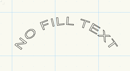
Why won't TAP fill the text? I managed to get it to work once but cannot replicate. What is the secret?
-
Solved: In pref's deselect "place as keynotes"
-
New Issue:
Using the callout tool to create a keynote list. Started of great, sequential numbers etc. Then I wanted to target an item that was already on the list, i.e. re-use number 4. When prompted to enter the call out text I entered the number that corresponds to the note (in this case #4) but instead of number 4 appearing the next sequential number appears (in this case 7). How do you stop the automatic numbering?
-
Either of your callouts would be fine with me. I have version 2015 and don't see the option to "extend shoulder". thanks for trying to help, I appreciate it.
-
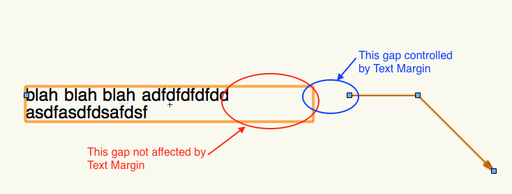
That's one of the things I tried and you would think that would work. It automatically is set to .047", I tried .001, even .00" no change and it would not accept a negative number. It seems to help with only one line of text, but if there are two or more it doesn't really do anything. See at new image.
-
Is there a way to close the gap between text and leader while maintaining left text alignment? Ideally I would to align all the annotations to the left but not have these ridiculous gaps.
I know I can play with the max. text width, but then i have to move the text body and fiddle with the handles of the leader etc.
-
This is one of the most confusing tools available. I'm sure I'm doing it wrong because I don't think like a software engineer.
1. Should it be inserted in the annotation viewport? Where I assume it would take on the scale of the viewport. Or should it be placed on the sheet layer?
2. Well, skip question #2.
Guess I'm mostly just complaining because with some of these tools one never knows what units they are supposed to be working with (sheet units, drawing scale units)
Okay I played with it and figured it out. I ranted to soon!
-
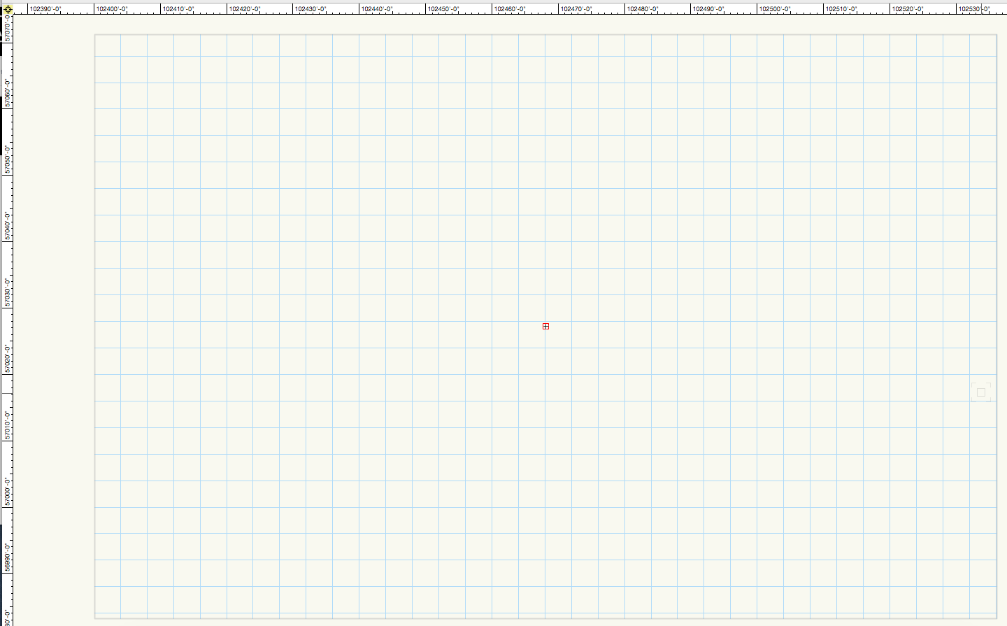
thank you kevin, didn't know that tool existed. however the process came with the warning that such a move would put the page far from the internal origin. is there something to do about that or should i even be concerned about it?
-
so after importing a dwg file and foolishly working on it for a couple of days i realized my drawing and "sheet" in my design layers was 10 miles north and 19 miles west of 0,0.
i could have reset the origin, but after reading a couple of threads here i decided to move all objects instead. now one question remains; how do i get my design layer sheet to move as it seems to be unselectable and immovable?
-
thank you mk that does help but i wish i didn't have to ungroup it.
-
What am I missing? I love the breakline tool. It easily creates perfect looking breaklines easily. But why can't you use the connect/combine tool or the trim tool to remove the portion of lines at boundary of the breakline?
-
Perfect. I knew It would be about a 45 angle, I kept trying the upper line. Still is kinda 2-steps but at least I understand better how it works. Thank you.
-
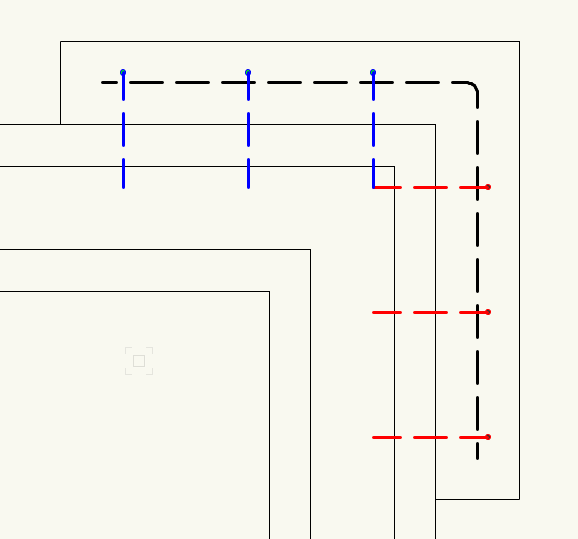
Trying and trying to find the correct fulcrum point and rotation direction to copy the red lines into the position of the blue lines. I get close, but then need to mirror copy them. Is it just going to be a two command task or have I just not figured it out yet?
-
Well it didn't really work. It left a little trailing piece of wall and an equal size divot from another segment of wall. The red rectangle is where I tried to clip surface. Yes my rectangle was placed accurately.
Surely someone has dealt with this situation before. Do I make several wall types/thickness and wrap them around? Tried the pilaster tool, works on one side. So really this is like a
3-sided pilaster.

-
Solved, I think. I placed the wider section of wall in the footprint of the hollow rectangle and then placed a rectangle over the lower left corner (next to door jamb) that I wanted to remove and used clip surface and it worked!
-
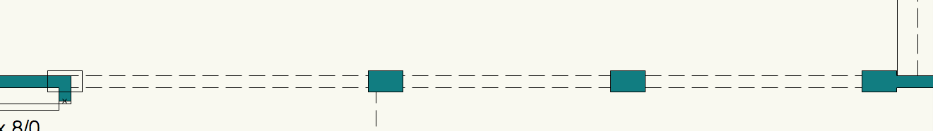
I need to show a thickened or offset wall. See image left side, hollow rectangle that matches the small wall sections in the middle and the thickened wall section on the right.
And what do wall offsets really describe? Changes to top & or bottom of wall segments? Or wall thickness like I am trying to demonstrate? Or just any change to the plane of the wall?
So, what sort of monkeying around can I anticipate in order to yield the results I want? The typical walls are 3.5" and the thicker wall segments (casi columns) are 6".
-
Thanks to all for you help. I'm still sure where I want to put my floor slab. I don't usually show it on a floor plan view, but maybe I'll change my way of thinking! And I never considered putting the stair and floor slab on a unique layer. Hmm. So for now I'll adjust stair break and view. So these are my two simple options that I'll choose from.
Thanks again, I appreciate your time and suggestions.
-
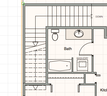
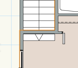
I moved the 2nd floor slab to 2nd floor layer - checked z heights, gave it a mocha solid fill to easier see it. The orange line is the floor slab boundary. Still the stair trumps. If I send the floor to the front with fill then the 2nd floor elements are not visible, without fill the steps in question are still visible. I think I'll just change the stair to view to 'above break only' and be done with it.
-
Okay, I do have a floor slab but I put it on the first floor layer. Do you make separate layers for floor slabs or include them with the level above?
-
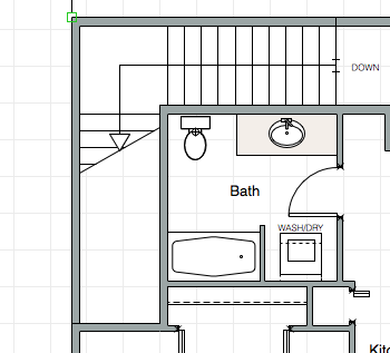
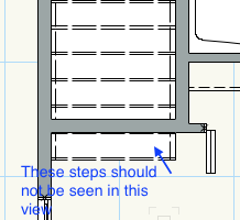
The attached clip is at second floor level. The stair is going down and below the wall and the two risers below the wall should not be seen. Is there a simple way of clipping the last couple of risers? Should I just make a little mask to cover them up or is there a proper way?
-
Working on an apartment building. Part of bldg is 2 stories, part is 3 stories.
Design layer for each story. Would like to have a symbol for each unit type. (4-unit types). Attempted making a symbol but noticed that any 2D geometry disappears.
Is this normal behavior?
Should I just create each unit type and then have multiple viewports on a sheet layer? I think annotations would be a nightmare.
Ideas, suggestions, ...
-
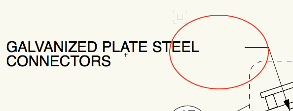
Has anyone noticed that if you use the callout tool with a bubble style "circle" if you have a single digit number like for a keynote the circle is one size, but if you have double digit number then the circle adjusts and is larger?
Who thinks this is a good idea? It makes the annotations look sloppy.
Why can't we have fixed size bubble?
I know...use the keynote tool. But I want to add a leader with arrow as shown in attachment.
-
 2
2
-
-
Yes I'm sure that is where the issue is. As my design progressed I needed to create a split level portion of building and I tried to set up layers, levels, stories to accommodate and obviously blew it. My windows and doors however show up just fine! I have more reading to do, I don't fully understand the binding options or offset options. I wish I could just create a story pole with all my z heights.
Thank you.


2d/3d symbol
in General Discussion
Posted
I have a symbol that came from autocad that I have edited. I added text (actually text along path), then exited the symbol. The text disappeared.
Why? All geometry was 2d and on same layer and class as the text I added. As a text I went back and added normal text. It remained after closing the symbol.
So then I started the edit symbol again and selected the 3d option. The text along path that I had originally created was there. I cannot get it to be visible in a 2d top/plan view. Any direction would be appreciated.