


jmartinarch
-
Posts
331 -
Joined
-
Last visited
-
y e s
-
Clip. Clip the smaller shape not add it. Sorry for waisting your time.
-
LOL yes that is correct. When I try the smaller shape disappears. I'll start over and see if I can make it work.
-
They don't have a fill, but they are not closed. They must be closed I suspect. Thank you.
-
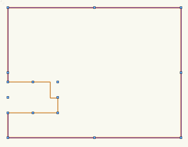
Why won't these two surfaces combine? Same layer, class, etc. I just changed the line color and thickness of one to differentiate one from the other. After selecting them I right-click select add surface and the inner surface disappears. The larger was created with the rectangle tool and the smaller faceted one with the 2d polygon tool. The OI palette says they are both polygons.
-
Thanks, for the suggestion. I hadn't thought of that strategy.
-
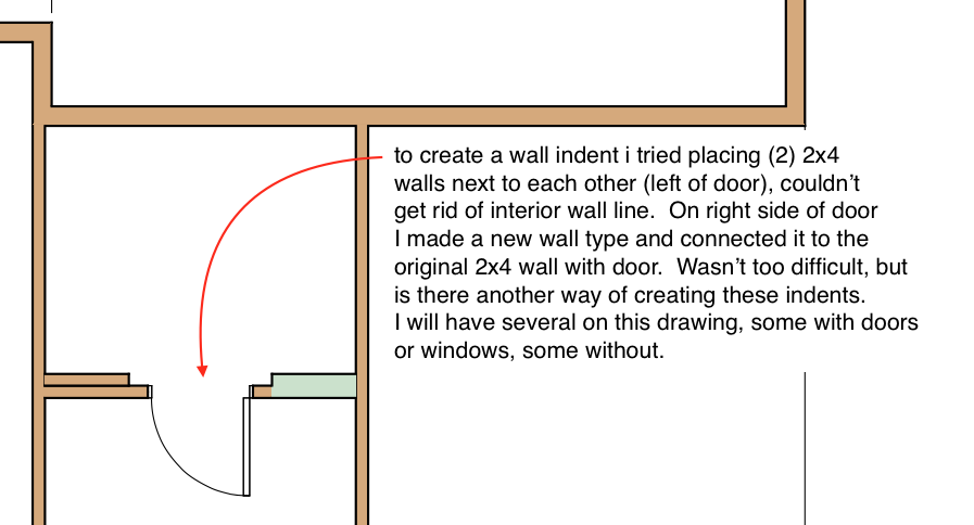
I have several of these instances where I need a wall recess. Some with doors, some are just wall features. Is there some easy magic way (that one key to press) of doing this? I think using two wall styles is easy for plan view but then you have two walls not one continuous. Will that matter? Thanks, JM
-
So the sheet layers are not coming through cleanly? This is a pretty nasty looking dwg. I think you need a big cup of coffee and slowly click, check and turn classes or layers off to get where you need to be. Was this something else (file type) before it became a .dwg?
-
I started to add a callout, but decided no. However it had populated the legend. Now I have a number of a keynote, with the note X. I can remove the X by unchecking the box in the OI palette. I also see re-use unused positions. Can someone explain how to do this? I don't want a blank in my or an X in my legend. Thanks
-
A strange thing has happened on the last couple of projects. In one case a few dimensions (text only) changed color from black to blue. In the other case both dim. lines and text changed. In some of the instances they appear as black in design layers but blue in sheet layer viewport, in some cases they appear as black but print blue. What could be going wrong? I've checked text styles, and the individual dimension strings to see if the attribute was changed but all are set 'by class' and the class is black.
-
Sorry I'm kinda dumb with VW, but when you say you created a bounding box, did you use the rectangle tool or is there another tool hide somewhere? Are you trying to create a viewport over another viewport? I tried with the rectangle tool but received an entirely different message. I have to start with View>create viewport, then set up a crop for the viewport.
-
thinking of upgrading to OS Sierra
jmartinarch replied to digitalcarbon's topic in General Discussion
Anyone with VW2015 that has made the upgrade? -
I got it to work.! I started a fresh file, created a slab layer: top at '0' , created a foundation layer: top at -10.25 (thickness of joists and pw). Created two walls; one stemwall 24" height, top bound = layer elevation, top offset 0" , bottom bound = layer elev. bottom offset =-24". Second wall (footing) 8" height, top bound= layer elevation, top offset -24" (or bottom of stem wall, bottom bound = layer elevation, bottom offset = -32" (stem height + footing ht). then in iso view I changed numbers and watched results. now it makes sense to me. Thank you for your patience and help! Now putting in that 2x6 mudsill between the slab and top of stemwall.....
-
Sorry Alan I couldn't open your file.
-
I got it to work but don't understand VW methodology at all. I created a test file: foundation layer elevation of -10.25" (presumably top of foundation) with a wall height of 32" (8" footing, 24" stemwall). Created a foundation wall type with height of 24" top bound by layer elev. It automatically gave me a top offset of 24" (which I honestly do not comprehend), bottom bound by layer elevation, bottom offset of 0. Then the footing (wall) 16" thick wall x 8" tall. In the OIP the height is -8" and top offset is -8". Graphically it looks correct. In an iso view it looks correct. Why is the height of this wall a negative number while the height of the stemwall a positive number when both are bound by the layer elevation? Untitled 3.vwx