CW2020
-
Posts
128 -
Joined
Content Type
Profiles
Forums
Events
Articles
Marionette
Store
Everything posted by CW2020
-
Link/Connect Design Layer Viewports Between Multiple Files Online
CW2020 replied to CW2020's topic in General Discussion
Thanks, Mark -
On file hosting websites (such as Dropbox and Google Drive), can you link /connect VWX files?
-
That's a big help, Evan. I can't say it enough though, having been taught the Layer Plane is your 2D Top/Plan plane, it's counterintuitive to consider the Screen Plane applies to 2D objects. When you/someone looks at the image above for the video, the Layer Plane is clearly 2D flat on the layer. I'm not even clear (only because I don't work with it) in what application one would want an object flat on my "screen" as shown in the image above and that video... maybe for a "working" plane. In fact, are you saying I should be drafting floor plans on the Screen Plane and not the Layer Plane?
-
Thanks! That makes sense. All of this is sorta new on me, as it's never been an issue. I still need to research the Layer Plane/Screen Planes though, as I'm fairly certain I was taught to draft on Layer Plane if working in 2D... after all, when you open a new file it defaults to Layer Plane and Top/Plan... and that video I shared above ( ) makes sense to me. Even the screenshot of the video reads that the Layer Plane should be "2D Top/Plan View." Thanks again everyone! You're all appreciated!
-
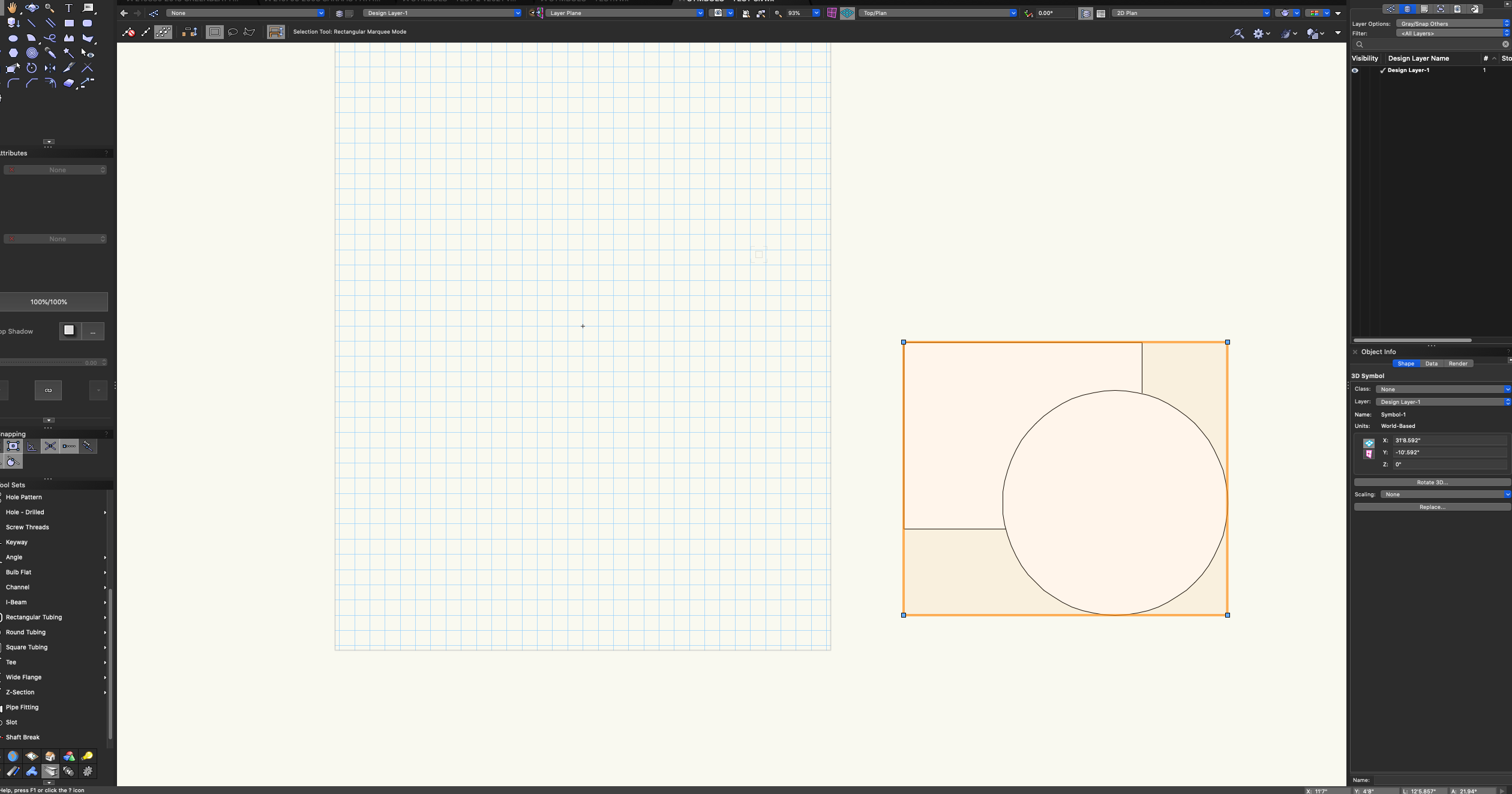
Yes, I get the parametric objects vs symbols, but as far as there 2D/3D existence I perceived a correlation. That said, and getting back to my first upload and question, why is it that when I create a symbol in Top/Plan on the Layer Plane it results in a 3D symbol? In the attached, I drafted two objects and then created a symbol using the same technique I always use and the ones used in video instructions. But why are they 3D? I'm also including a screenshot of my VWX window, but it's standard... no customization. And again, to all of you, this is me simply not getting it... I'm certain you're all correct. SYMBOLS - TEST 3.vwx

-
Sorry I'm so slow to "get this," Pat. For background, this came up when a client commented to me I had different iBeam symbols... some of which were 3D and some were 2D in the same file (note everything drafted is in Top/Plan). He went on to say that he could not snap to the 3D iBeams. Firstly, I have no issues snapping and seeing curser cues to the 3D iBeams (I attached a file of the iBeams). Regardless, when I select an iBeam (new) from the Tool Set it's in 2D and I wouldn't even know how to convert it to 3D because I don't need to do that. Yet, several of my iBeams are clearly in 3D. So as a test, I made a number of passes at making new symbols (including following the video above and others) and when finished I could see that they're ALL 3D symbols in the Object Info Pallet. So again I don't understand how to create a 2D-specific symbol. Also (FYI), you stated that "The Screen Plane objects are shown when in Top/Plan view." I trust your knowledge and experience, but I was taught to keep all objects for Top/Plan view on the Layer Plane for the exact reason explained in this VWX issued video. I think ultimately, I need to dig deeper into this... SYMBOLS - TEST 2.vwx
-
Thanks everyone, but this is still unclear to me. From the start of the video, the 1st symbol created reads as a 2D in the Object Info Pallet. I created the two symbols in the attached file over the course of a project... one is 2D and the other 3D. However, I believe I take the same steps every time I create a symbol. SYMBOLS - TEST.vwx
-
Mind you, I don't tend to have any issues with having a 3D symbol in a 2D environment, how does one make a 2D-specific symbol?
-
For the past several months or so, I CONSTANTLY have my plan view switch to orthogonal. I've reviewed any shortcuts related to view I can identify and may be triggering accidentally, but it's still happening... I had just been accepting it as a bug, but I can't imagine other users work this way. Any feedback would be appreciated. Thanks.
-
Ah ha! That makes sense, now. I would've chased my tail a few more rounds without your help. Thanks, bgoff!
-
I'm working with a plant symbol who's tick mark is not centered. I looked into other postings that reference editing this in "plant geometry," but that's not clear to me. I have tried locating the tick mark in the 2d/3d symbol, but it doesn't appear. Any input is appreciated.
-
Yes, that's it! I think Pat touched on those settings in recent user group meeting, I just couldn't remember. Thanks to you both.
-
I do use it with some frequency, the more I think about it. But yeah, sometimes I wouldn't mind having it off.
-
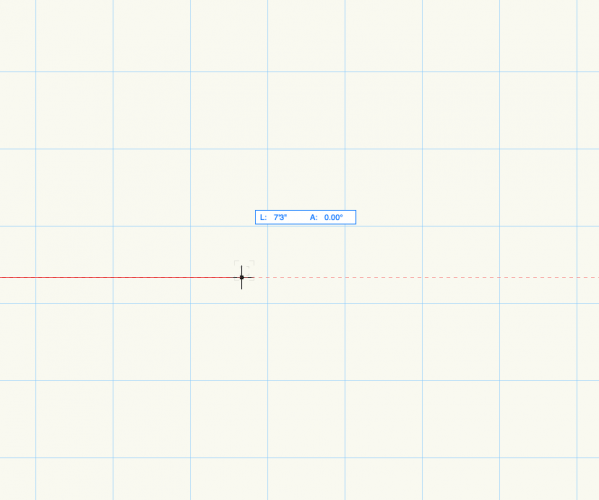
I'm referring to the info that appears on the cursor while drafting (see attached). I guess I use it occasionally, but sometimes it's just one more item on a screen.... on technical drawing I think I'd leave it off if possible.
-
The cursor datum could be turned off, correct? If so, please share how to do this.
-
Red "Infinity-like Symbol" Appearing on Section Marker
CW2020 replied to CW2020's topic in Site Design
Thanks, Pat! -
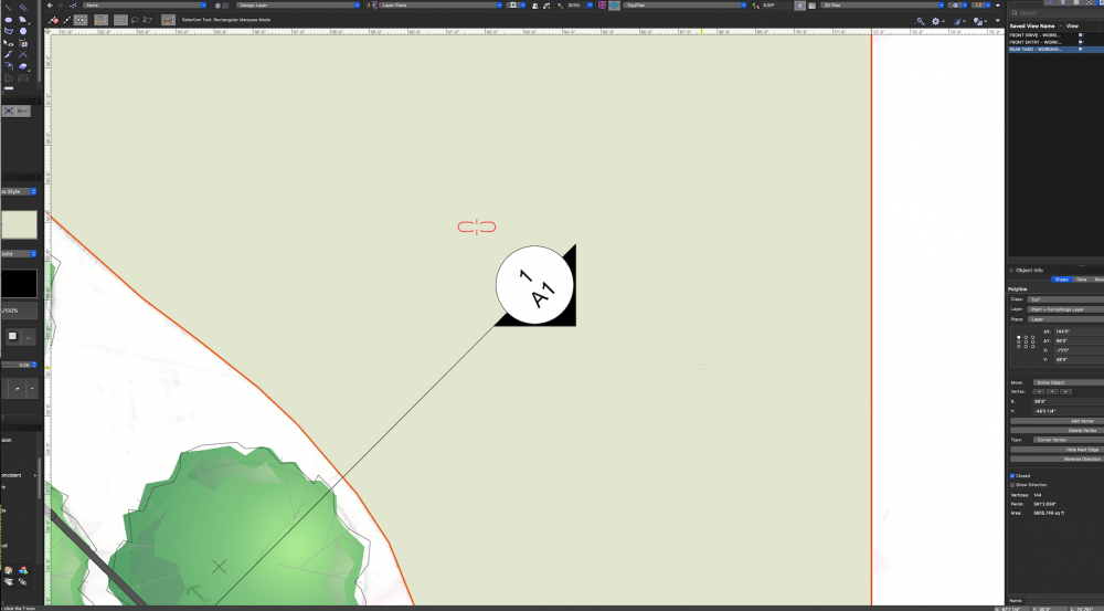
I've attached an image of this red symbol that's been appearing in recent days on my section makers. I don't think it's Landmark-specific, but that's what I'm working in today.
-
Wall Style Components and Hatches Disappearing in Annotations
CW2020 replied to CW2020's topic in Architecture
A colleague solved this issue for me. There's a setting in the Object Info palette for "Detail Level." Some of the viewports on the project in question had this set to "Low" to help increase the speed of the viewport update. Adjusting this setting to "Medium" has resolved my problem... allowing me to draft styled walls on annotations where the component attributes read clearly. -
Text Does Not Remain "In-Place/Correct" when Flipping/Mirroring Symbol
CW2020 replied to CW2020's topic in Architecture
It's some "file" setting, maybe. Because I have a reference file from a client that has wall tags that can be mirrored while maintaining the proper text oreientation. I even tried copying and pasting those same symbols into my working file, and they're all wrong. Thanks though, Pat! And yes, the entire file just seems buggy. -
I believe I encountered this before, but don't remember the workaround. I created Floor Plan view wall tag symbols that include a digit in each. When I flip/rotate the symbol/wall tag, the numbers flip/rotate, when they need to remain in-place and upright. I did check that Adjust Flipped Text is on in Document Preferences and Viewport Advanced Properties.
-
I was brought in on a project that has utilized the cross section viewport tool to establish the outline of the build and then drawn its components over this outline on the annotations. One prominent element of this move is to use styled walls vertically on the annotations; typical interior and exterior wall types. However, the components of the walls disappear in several 'but not all' annotations. This is also true of hatches used in a similar application. I've recreated this wall and hatch condition with no issues, but with there being multiple viewports and walls/hatches configured on multiple sheets already, I figured I'd ask if anyone's familiar with the problem... as I can't imagine recreating all these new viewports so that there's no issues with the wall components showing. For what it's worth, I've checked that all classes are on and such, but have not spent hours (yet) sorting this out. *Note my VWX program has been buggy since upgrading to 2020, but I'll start a new thread for discussion.
-
PROBLEM - Drafting in Color / Publishing Black & White
CW2020 replied to CW2020's topic in General Discussion
All very helpful ideas! I'll try to implement some of these strategies and follow-up with feedback soon. Thanks again, everyone! -
Square Suddenly Appears when Entering Viewport
CW2020 replied to CW2020's topic in General Discussion
BOOM! Yes. Thanks Tamsin. -
Yesterday, all of a sudden anytime I enter a viewport a neon green square appears on the design layer seemingly the same size and location of the viewport's crop. Has anyone seen this happen or read about this in a previous thread? Note this is occurring across all files I've worked on since yesterday and I did not create these files.
-
PROBLEM - Drafting in Color / Publishing Black & White
CW2020 replied to CW2020's topic in General Discussion
Thanks for all the feedback! Haven't hadn't a chance to dive back into this issue, but will keep you posted.