


Mitchell (the other one)
-
Posts
87 -
Joined
-
Last visited
Content Type
Profiles
Forums
Events
Articles
Marionette
Store
Posts posted by Mitchell (the other one)
-
-
Additional leader lines each with their own arrowhead can be added. What I'm looking for is the ability to add additional leader line points so an existing leader line can be have more bends added as a detail is developed.
-
I've looked through the Object Info Pallette (VW 2019) and have not seen a field where I can change the number of leader points - if you can point me in the right direction it would be appreciated.
-
Is there a way to edit an existing callout to add more leader line points to add a 'bend' or two to the target line? When you create a new callout you can set the number of leader line points. However, if I am modifying a drawing and need an existing callout target line to have a new corner or two, I haven't found the way to add more points. Do I have to create a new callout with the new number of line points and replace the existing callout?
-
On 7/20/2019 at 9:23 AM, Tamsin Slatter said:
Here it is in 2017...
And here's the cake (soon to be smothered in chocolate icing and raspberries...)!
That cake may be the best rendered model I've seen here . . . . nice work!
-
 1
1
-
 1
1
-
-
I'm looking for a farm tractor symbol in plan view. Does anyone have one they might share? Or point me towards a good resource?
Thanks.
-
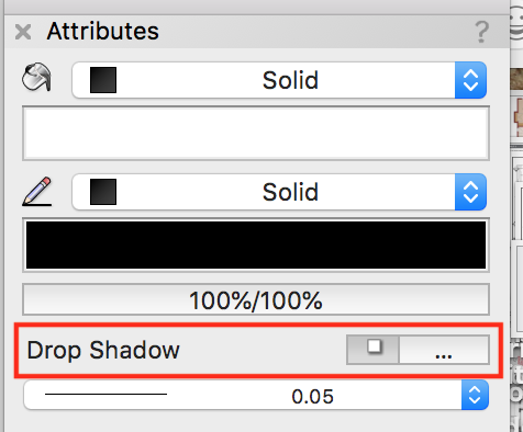
On / off button in attributes palette.
-
1
-
-
Now that I understand the spacing you want to control (sorry I missed that), I kept trying but no solution either.
-
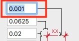
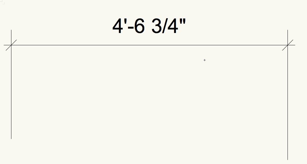
The topmost field will adjust the distance between the text and the line.
Two examples, the first with the default spacing, the second adjusted to a tighter spacing.


-
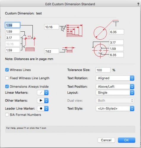
Try, File > Document Preferences > Dimensions > Custom, then create a custom dimension, Select it, then Edit and you should be able to control all aspects of the dimension.
-
3 hours ago, Alan Woodwell said:
This would be a hard one to have a plugin without engineering input because of the grade of timber you have available to you would affect the size of members.
That doesn't seem to be an issue in our market. Trusses here all use 2x material, 2x6 being standard. Occasionally we will use a 2x8 cord but with a minimum heel height of 11" to get the code required insulation values at the exterior walls, top and bottom cord dimensions have never been an issue with a flat bottom cord truss. I agree with you for a mono slope truss or a scissor truss, there is less space within the truss to work with and member size is important.
3 hours ago, Alan Woodwell said:I use the framing member tool a lot which will get all the rafters and ceiling joists in
I look upon the Create Roof tool with lust - I love what it can produce. But it dimensions to a birds mouth cut, I haven't figured out a easy way to pervert this tool to calculate heel hight which is measured to top of cord at face of wall.
its a tedious task
Agreed - and this is why I have raised the question.
Thank you for your reply.
-
Good afternoon, I am a long time Vectorworks user, new to the Tech Board, (this is my first posting), I am a subscriber to the older Vectorworks User Discussion List.
My first question is for those that create models of buildings that will be built with roof trusses. How are you modelling and controlling (manipulating) the profile of the roof trusses?
Here (in western Canada) the vast majority of our houses are built with roof trusses. During the design I may adjust the depth of the truss heel and the roof slope several times as needed to meet the overall building height allowed within the site zoning. Without a roof truss tool (if there is one I'm going to look pretty dumb) are you drawing a truss in elevation and then extruding it for the model? Creating a roof face and then positioning it to allow for a heel depth? As for the final building section, I'm not looking for the software to suggest a truss type (Howe, Fink, etc.), just provide a profile using the parameters I control as the designer and then the truss manufacture can build to fit the profile.
Thanks.


Callout Tool - Leader line points
in Wishlist - Feature and Content Requests
Posted
I would like to be able to edit an existing callout to add more leader line points to add a 'bend' or two to the target line. When you create a new callout you can set the number of leader line points, however, if I am modifying a drawing and need an existing callout target line to have a new corner or two, there isn't an option to add more points. At the moment I now create a new callout with the new number of line points and replace the existing callout.