


Eaglerulez
-
Posts
36 -
Joined
-
Last visited
Content Type
Profiles
Forums
Events
Articles
Marionette
Store
Posts posted by Eaglerulez
-
-
Hi Letti,
Thanks so much for this! I will give it a whirl and will keep you posted!
-
Awesome! Let me try this out on my end this is a very helpful step in the right direction I believe!
-
Hi there,
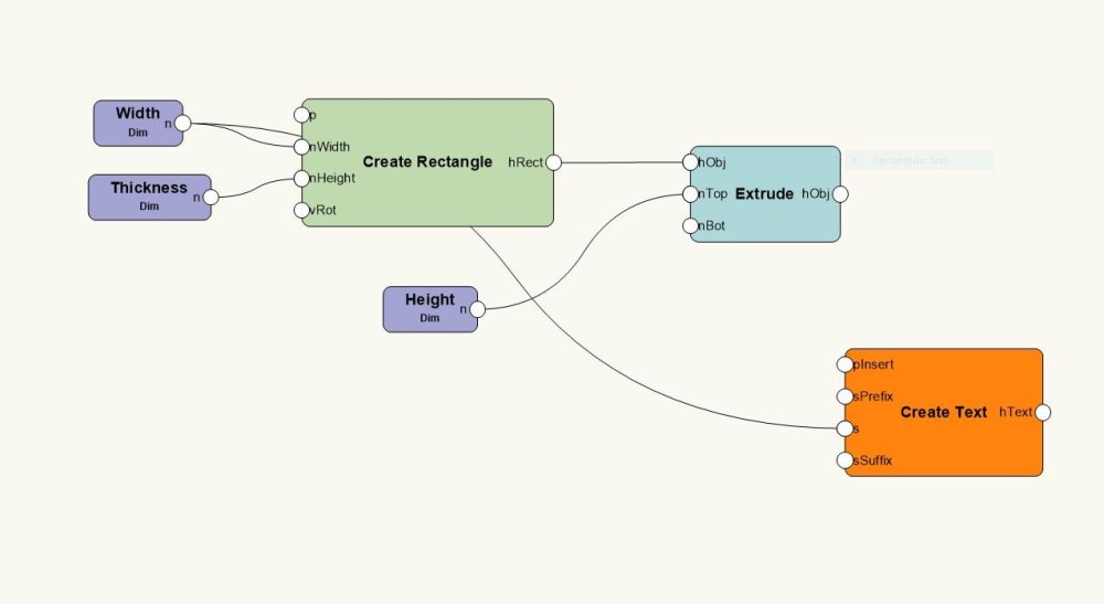
I am trying to make a simple Marionette node where I can make a cube extrude and have the dimension for the extrude displayed next to the cube.
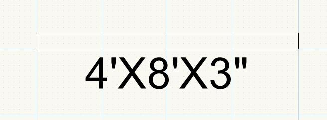
I have attached a screenshot of my current Marionette network, my current output, and my desired outcome.
I think I have (2) main challenges that I haven't been able to figure out.
-How to get dimensions to display with unit values and not several zeros behind it.
-How to get multiple dimensions to be added cleanly within a single string/text box like my desired outcome.
Any thoughts on how to best achieve this?
Thanks so much!

-
1 minute ago, markdd said:
Maybe the thing to think about is using layers for this instead. Each Truss or area that you want to isolate is on a different design layer. I often use the "Show others" Layer option and then use the Activate Layer Right-click command to toggle layers when moving around the drawing area.
If you do use the Show Snap others option with Classes, try reducing the number of Snap to Object points to just a couple in the Smartcursor settings. By default, they are all on, but there is a choice of seven and eight and I often find that reducing down to just a couple makes a huge difference to the "busy-ness" of the SnartCursor.
Yes thank you! I thought about using layers, my problem is that I find I have to be fairly methodical with my layer order for things to stack properly and have found that to be a little limiting/difficult to deal with when working with a client who is changing things on the fly.
My problem isn't so much the busyness of the smart cursor. It's just that I literally can't select any of my symbol geometry in "Show/Snap" because all of the geometry is technically in another class still.
-
7 minutes ago, markdd said:
The short answer with Symbols is no.
However, with regard to Truss objects, there is a mechanism in Spotlight Preferences called Modify Truss Object Color in the Loads and Rigging section which makes an exception to this rule and will allow the geometry of truss objects take on the Attribute properties of a Class or the Attributes palette itself.
Thank you. The problem isn't so much the attributes, it's the fact that I like to select classes and leave myself in "Show Snap/Others" so that I do not accidentally interact with other objects on my drawing. What I run into when doing this is that I can't really drag my truss symbols because I can't select the lines and geometry that comprise the symbol since it is in another class.
I mean worst case I can select in "Show Snap/Others" and then move things around in "Show/Snap/Modify Others" but wondering if there are any other work arounds/approaches to this.
Thanks again!
-
Hi there,
I was curious if it was possible to have all the objects in a symbol inherit the symbol's class.
For instance I have a lot of truss symbols that typically reside in a "Truss" class. On larger projects I will make different truss classes. For instance "Truss-Downstage" "Truss-Upstage" etc.
While the symbols themselves go into their respective classes the sub objects that actually make the truss are still stuck in the "Truss" class which can make selection and visibility a little awkward.
Any thoughts on how to best overcome this? I pretty much want it so that if I put my truss symbol into the class "Truss-Downstage" everything associated with that symbol is assigned to that class.
Thanks so much!
-
2 minutes ago, klinzey said:
Make sure the data you are supplying the Vectorworks symbol is in candle power or peak candella, not Lux, Lumen or some other value. (It does NOT use the value from the VW light emitter.)
With that said Vectorworks uses a very simple cosine squared falloff calculation based on the distance from the source.
It does not take into account dimmer value, color, shadows, reflections or any other objects in the drawing.
Hi there,
I am using a stock Vectorworks library symbol and have confirmed that it is using candellas.
Honestly not looking for Vectorworks to calculate things like color, dimmer value, etc. Just want it to get within spitting range of the manufacturer reports otherwise there's no point in using this functionality. I figure there may be something I am missing in how I have things laid out in Vectorworks?
-
 1
1
-
-
Hi there,
I am interested in using the Photometer and Photometric grid tools to predict staging light levels.
As I was playing around with the tools I was getting footcandle readings that seem to be much higher than listed on the manufacturer's report. For instance at a distance of say 16' when I would expect to get around 300 footcandles (based on the manufacturer's report) I am reading 450 foot candles in Vectorworks.
Are there any tips and tricks that I can use to get a more accurate prediction from Vectorworks? I tried playing around with where the photometer was placed (how centered on the beam it was, etc) but still no dice.
I don't mind some variance, but it seems like Vectorworks is substantially higher in its predictions than what the manufacturer's report shows and if anything I'd rather have it the other way around.
Thank you!
-
40 minutes ago, m.graf said:
there is one chance:
is a 3d component in your Marionetteobject or only 2d on the screen level?
It is a 3D object at screen level.
-
2 minutes ago, m.graf said:
hi Eaglerulez
no extra node - what's your Vectorworks Version?
i see the Z in my "Objektinfopalette" in VW2019/2020/2021
greatings M.Graf
I'm running 2017, could that be the problem?
-
5 minutes ago, m.graf said:
similar to symbol's "Objekt Info"
greatings M. Graf
Thank you, however that is not appearing on my end. Do I need to add a node to show that property box?
-
Hi there,
This may be a silly question, but after a few hours or research I'm actually having a hard time finding this/figuring this out.
I'm doing some basic testing with Marionette objects and have an object that is an extruded rectangle which I can change length, width, and extrusion height with.
That works perfectly! However I would also like to set the "bottom Z" of my object after it is made.
What is the best way to approach this? I'm actually not seeing any nodes that really call this out, nor do the tutorials I find explicitly show how to set a "bottom Z" for a 3D Marionette object so was curious what the best way to approach this typically is.
Thanks so much in advance!
-
Hi there,
My company uses slightly different deck than what is offered in the "Stage Deck Tool". We were wondering if it was somehow possible to integrate our deck symbols into this tool.
Perhaps more importantly, the "Create Stage" functionality is a great time saver. We were wondering if it was possible to utilize our deck symbols in this functionality as opposed to the stock symbols.
Any thoughts?
-
Hi there,
I have a Marionette Object that has (2) radio buttons to select pre-defined colors and then I have a checkbox to mix a custom color via RGB sliders.
Everything is working perfectly, however I was wondering if it was possible to gray out the sliders until the "use custom color" checkbox was selected.
Is something like this possible?
-
Hi there,
I am trying my hand at some Marionette scripting and here is what I am trying to accomplish.
Would like to create an extruded rectangle and then give it dimensions which can be viewable in the Top/Plan view as well as in an Elevation view.
I have no problem with drawing and extruding the rectangle, but here are my challenges thus far:
-I am using two dimension inputs to create my rectangle (one for width and one for height). Ideally I am making a single text box that says " 4'X8' ". Is there a convenient way to get my rectangle dimensions into a single text object? Right now I can get width into a text object and I can get length into a text object, but I can't get them both simultaneously.
-When I do get my dimensions into a text object their dimensional values aren't represented. For instance they will read 48.00 as opposed to 4' or 48". Is there a way to correct/change this?
-Lastly I am having a hard time getting my text to orient both in 2D and 3D. On the 2D front my text is centering on the rectangle based on the text's insertion point, which is left justified and not necessarily the center of the text bounding box (which is what I really want). On the 3D front I am just generally having a hard time orienting the text in a way that is visible in a 3D view. It tends to lie flat as opposed to standing like I would like.
I am pretty new to Marionette so I am sure some of this is basics that I may be missing. I've searched through the forums pretty extensively and it looks like there have been conversations about this type of thing, but no clear solutions that I came across.
Thanks so much!
-
6 hours ago, Pat Stanford said:
No good tutorial I am aware of. Let's make one. Can you post a file with a sample of your flat symbols so I can think about the best way to construct?
Hi,
Please see attached file here. At the moment they are basic extruded rectangles for simplicity.
-
15 hours ago, Pat Stanford said:
Not possible using symbols by themselves. The only information that can be displayed singing the Link Text To Record command is data in a static record. You would have to change both the symbol and the record information as you are doing now.
A couple of possibilities:
1. Use a script to find all of the custom sized symbols and programmatically update the information in the Record which is linked to text in the symbol.
2. Create a Plug-in Object (PIO) rather than static symbols. Then when you change the values in the OIP (Object Info Palette), the symbol and record would both be updated at the same time.
Got it! I think a plug-in object could work quite well. I may be missing something but is there a tutorial or resource which explains how to make Plug-in Objects?
15 hours ago, Pat Stanford said: -
Hi there,
I am diving into the world of using worksheets to help keep track of symbols. We happen to draw a lot of wall-flats which vary in size based on the production that we are working on. We have a few basic sizes as symbols, but also have a symbol that is pretty quick and easy to modify for when we run into dimensions that are outside of our basic sizes (which is somewhat often).
Right now if we were to encounter a wall-flat that is outside of what we already have in the library. We would have to update our template symbol to the new size, duplicate the template as a new symbol, and then update the record information appropriately.
We were curious if there was a way to make it so that when we updated the dimensions in our object info properties, that the record would also update appropriately. So for instance if we had a 4'X8' wall flat and modified it to become a 4'X9' wall flat, that the record would update as we changed the dimensions in the object info properties.
Likewise, we were curious if it was possible to link text to dimensions in the object info properties as well. So if our symbol had text associated with it which read "4'X8' wall flat" that it would automatically update to "4'X9' wall flat" as we updated dimensions.
Any thoughts on whether something like this is possible?
-
+1 As well. This is absolutely essential, especially on the spotlight side of things. It's the #1 thing that I dislike about Vectorworks.
I also feel like this would be fairly easy to accomplish.
-
To echo the thoughts of the majority of the people in this thread. I understand the logic behind these symbols bringing in their own classes but there needs to be some flexibility for users to tailor classing structures in a way that makes sense for them.
-
Well the crux of the problem for me is just all the garbage classes that the symbols bring in. A lot of my templates, etc. are ruined by the fact that my intelligent light (which is in the intelligent lights class) brings in 4 other random classes that I have no option to make visible in viewports by defualt. If there was at least a global setting that allowed for new symbol classes to be visible by default that would be awesome.
-
I just don't understand why I have to have a "Lighting-Moving Light Radius" class a "Lighting-Architectural" class a "Lighting-Incadescent" class, etc. Is it not possible for Vectorworks to go "Hey this guy wants this light in his "Lighting-LED" class...all these subclass can now be re-mapped to that"
I can get the 'hardcode" for using something like Vision, where things need to speak to each other...but maybe have an option to turn it off?
Beyond just lighting instruments though, other tools seem to do the same thing and it's confusing and disorganizing for no reason.
If I can add...it makes me really question why I'm buying $2500 software if it's just going to be needlessly disorganized. No other piece of CAD or design software that I have used gets like this.
-
Whenever I bring in a lighting instrument it also brings in a slew of its own classes.
Is there a way to have this not happen in Vectorworks 2017? It's wrecking havoc on my organization.
Thanks so much!
-
In the options, you can shift the plates to be in or out, if you set them to in, then they will be inside the limits of your curtain. Just like in real life you would not use a base that had a center hole, in the program you need to tell it basically what type of base to use.
Even when I set "In" and "Out" points on my bases the base plate is still over the edge of a wall by 3/4" every time.

Displaying dimension next to cube made in Marionette Network
in Marionette
Posted
Hi Letti,
Okay so everything generally is working well with this custom node however even foot measurements are not displaying quite as cleanly as I'd hope for.
Basically if I type 5' in for the DIM the output ends up being 5'" instead of 5'. I think this is because the dim input automatically rounds 5' to 5'0" and your node maybe rounds the zero down but does not delete the inch marker afterwards? I think my ideal output would be 5' as opposed to 5'" or 5'0".
Any thoughts on how to best address that?
On the positive side 12'6" gets displayed properly. 3" gets displayed properly so those work well!
Thanks so much in advance for your help!