


Jbscalia
-
Posts
23 -
Joined
-
Last visited
Content Type
Profiles
Forums
Events
Articles
Marionette
Store
Posts posted by Jbscalia
-
-
I found them by looking up how to create a cast in place concrete footing:
Inspector Jack is somewhat down in the webpage.
-
hi all,
I've been trying to folllow InspectorJack's instructions for creating a new class for my the poured-in-place concrete footing pads, but my VW2022 is now somewhat screwed up. It seems that when I set a concreate texture for the new wall class, the wall really doesnt get created. Behavior is otherwise normal, as he new "wall" as there is nothing else anywhere near where I'm clicking. Could this be a result of of a bug with my Dell XPS15? The biggest quest I have is, how do I get the behavior back to normal without using the new class?
--
Jay
-
I didn't realize until after posting my question that the upload failed, and I just tried to do so again, but it failed as well.
-
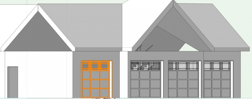
I have yet another issue that I haven't been able to solve. On the home I'm designing, the garage is at lower left front diagonally from the main structure. The first floor extends to connect the garage, while the 2nd floor simply is squared off and the lower left corner of it, sits on the nearest garage wall.I've attached the plan so anyone can see it.
Now the issue is that the first floor extension needs a 6/12 roof applied to it. I tried placing a polygon over these 2 areas and tried AEC create roof, but it didn't quite look right as it did not really extend much to connect to the bonus room over the garage roof. In my old Microstation system I could just draw a line on the second floor at that corner and project it onto the garage roof, but I'm missing how to do this in VW 2022. I'm open to any ideas for getting this to work.
-
ok, things don't look quite right. With a bonus room above the garage, should I rework the first floor walls so they terminate at the bottom of the 2nd floor, than extend the 2nd floors walls up to the roof? As it is now, the grouping of the 3 windows appear to be floating in space on the top view. The wall extension from the first floor layout is showing the breaks in the wall where the garage doors are.
-
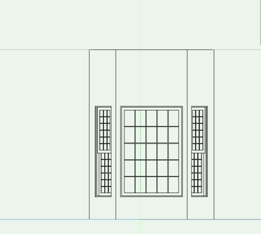
The garage is now looking correct, but I'm wondering about one more item. I've places a grouping of 3 windows in the bonus room above the garage, a paladium window flanked by 2 slightly snaller windows. Currently I have them on the first floor layout, with the elevations set to around 15' , but I'm wondering if I should move these to the 2nd floor layout, as I'm not sure these will be properly drawn on the hard copy plans.
-
To get the garage doors to meet up properly with the foundation, I only needed to shrink the height of the foundation walls on that side, the remaining 3 sides could stay at their full height. So, the left/front side was reduced by 15". Yes, I still work in imperial units not metric.
-
Tom W.
i figured out why the fit walls to objects failed, The windows didn't break the wall properly. I have removed those and put new windows into wall, and it works perfectly now.
I do need to replace one of the garage doors now as the effort to lower the doors and the wall, screwed that one up.
-
 1
1
-
-
Hey Tom,
that worked for gable on the front of the garage, but not for the gable on the side near the front of the house. Well, it only sort of worked, I should say. When I did the Fit Walls to Object it did extend the wall, but it screwed up where the windows in that wall were, as in it made a void above the windows extending all the way to the roof. I don't know if it's something about how the windows are defined or inserted, but it does this fairly consistently. Any ideas?
And E|FA, thatworks but if I turn on the foundation layer, the foundation walls cover up the bottom of the doors. Is there a way to have the top of the foundation wall wrap around the bottom of the door?
--
Jay
-
also, on a different note, how do I get the garage doors moved down as the garage floor is 15" lower than the main level?
-
I'm back with yet another question. Sorry about that. This time as the embedded image shows, I cannot seem to get all the walls to extend up to meet the roof. Wall clipping for the roof object does show that 3 walls have been selected, the two end walls and the front facing wall, but the display doesn't show it. How do I get this to display correctly?
-
Thanks TomKen, I hadn't considered using a regular roof placement and then switching the face nearest the house to a gable. It looks right now.
-
yes, basically I want the same as the lower right image from your sample.
-
I've been looking at some bay window questions on the forum, but I have a slightly different situation. My model has a 2' cantilevered bump out with 3 windows set in it forming the bay window. Rather similar to a home I built in North Carolina some year ago. My problem is getting a roof to appear over it in VW 2022. If I just set a polygon at the top of the bump out and tell VW to build a roof, it does the wrong thing where the roof has a peak at the 1' mark, then slopes down toward the house again. The roof I need is one that continues to slope upwards at a 6/12 pitch until it intersects the house again. I also tried setting roof faces unsuccessfully. As I can't seem to accurately set the angles for the roof faces.If VW had the ability to draw lines at precise angles easily, maybe I could do it. but so far drawing those edges in causes them to disappear if render in hidden line Here's the rendering of the window assembly and the roof needs to appear at the top of this.
-
It took some effort, but I was finally able to get the roof properly placed with its correct size.
-
I must be dense or something. I can't seem to find a command beginning with the word Reshape.
-
Thanks, Tom. I used the polygon to draw the outline for the roof. I converted both the southern and northern edges to gables, but if I attempt to resize the length as it intrudes into the 2nd floor, it only drags the entire roof not resize it, which is not what I want.
-
I have a portion on the house i'm designing where a roof over the first floor has it's southern boundary limited by where the 2nd floor overlaps it. My problem with this, and I'm sure it's simple, is that VW2022 keeps saying it can't create the roof. What I've tried is to pick the other 3 walls on the first floor, then create roof, and additionally pick those same 3 walls as well as the wall bounding it on the southern edge from the 2nd floor. Neither seems to work, though, and I'm a bit lost trying to put the roof in. Can anyone suggest what I need to do?
--
Jay
-
Hey, Thanks for that, I didn't realize that needed turned on.
-
Dubman,
I have yet to upgrade to V2022 precisely due to reported issues like you're reporting. As such, I cannot open your drawing.I have attached my early working model here, if you'd like to see if your system demonstrates the same problem. I'm currently very much a beginner here, although I have extensive experience with Bentley's Microstation system.
-
I'm trying to include some bath symbols like Kohler sinks, bathtubs, etc., the problem I have is that the symbols do not display at all on my screen All I get is a small crosshair cursor and then a goldenrod box approximating the size of the symbol, but nothing appearing as the actual symbol. I figure this is due to a setting turned off or something equally simple, but I've been at a loss to find it. Can anyone explain why this is occuring?
--
Jay
-
I’m a basic newcomer to Vectorworks, but I have had extensive experience with Bentley’s Microstation CAD system. What I’m try to is get a first story wall to line up over the basement walls. My wall is a custom wall I created which has, going from the most exterior surface to the interior:
1) 0.5” Hardie Plank Clapboards
2) 0.5” air gap
3) 2” Rockwool Warmboard
4) a vapor barrier
5) 0.5” plywood or OSB sheathing
6) 2x6 studs @ 16” o.c. Cavities filled with fiberglass insulation
7) 0.5” Gypsum wall board
the basement walls are 10” cored Insulated concrete forms (ICF).what I would like is to be able to do is specify which component layer lines up over which component layer, if this make sense to anyone, say
Lining up 0.5” plywood with the edge defining the 10” concrete core, so that the exterior 2” ICF poly will directly match with the edge of the Rockwool. Unfortunately, I have not been able to figure how to line up these things, but in this case the edge of the Hardie Planks will be about 1” outside of the ICF edge. Any ideas on how to accomplish this?
—
jay

I need a way to change the wall finish on just a portion of the wall
in General Discussion
Posted
I've tried researching this to no avail. I have a new outbuilding design, a garage or barn, if you will, that I'm trying to match the house's style. The house is a grand Queen Anne Victorian. I've attached a jpg of the design. Basically, above both garage doors, I want to place a 10" blank band at the start of the gable, and above that I would like have it appear using cedar shingles with rounded bottom edges. Also, these elements should appear in different colors. I just cannot figure out how to make this happen. Anyone else have any ideas?
--
Jay