


sbarnesvta
-
Posts
6 -
Joined
-
Last visited
Content Type
Profiles
Forums
Events
Articles
Marionette
Store
Posts posted by sbarnesvta
-
-
Thank you for the reply, I have followed the instructions and I think this is a limitation of the 2d plan view.
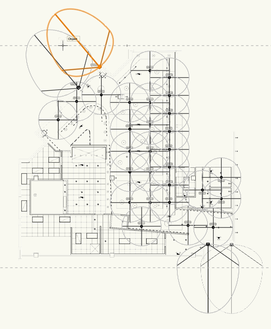
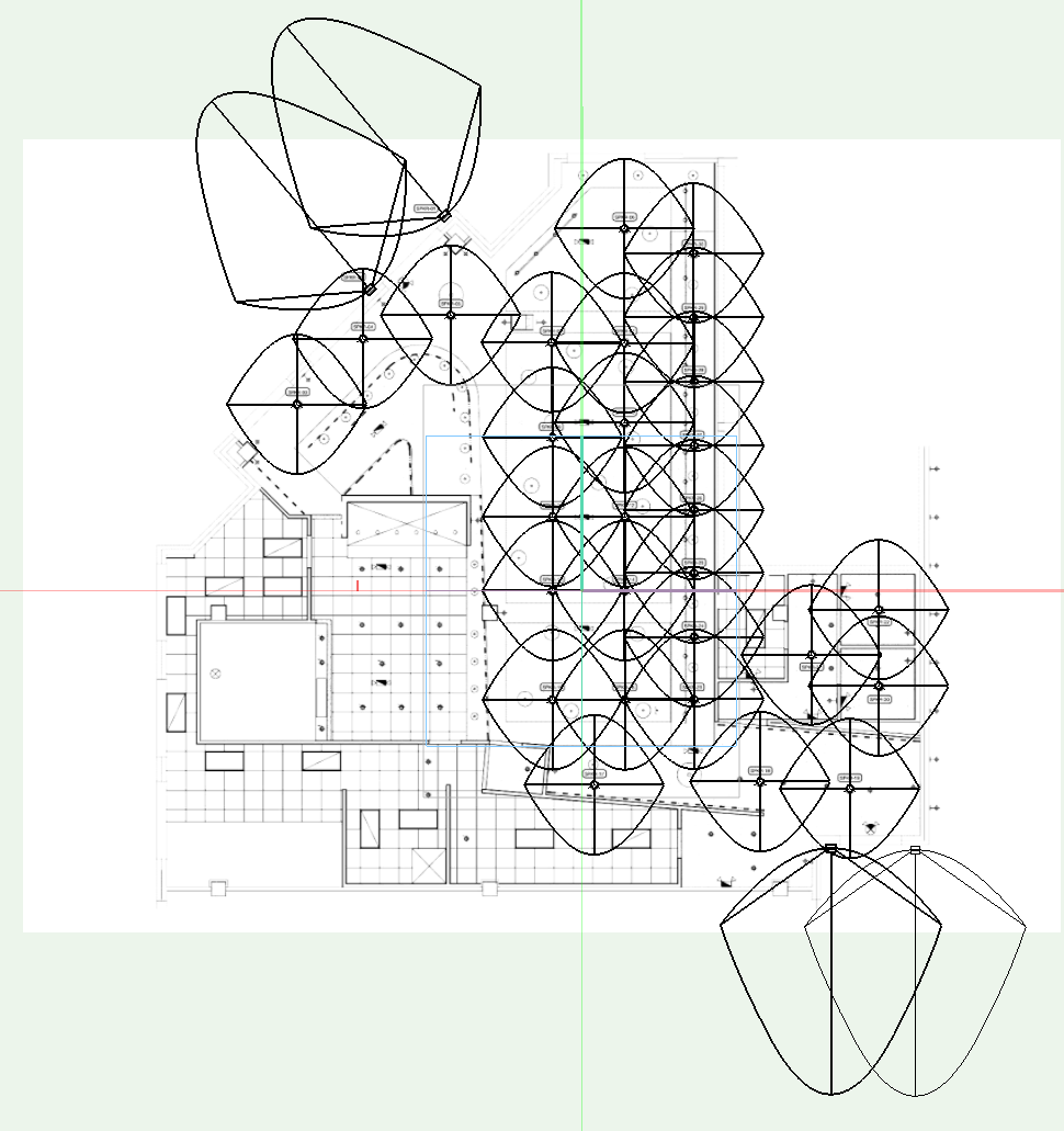
In the first screen shot you can see the line weight change to .5 and it get thicker as expected, but is not make up of a solid line it is a bunch of dots (not sure the technical term on this). In the second screen shot I change to an orthogonal view and it gives me the weight I am looking for, but it no longer representative of the conical speaker coverage pattern in the graphic.


-
Hello All,
Does anyone know if it is possible to change the line weight of the dispersion of a speaker? When I export a large drawing as a PDF, it is very difficult to see the speakers dispersion because the line weight is so small. I have dug around a bit, but have not been able to figure out if it is possible to change this somewhere. I have attached a screenshot below so you can see the issue.
Thanks in advance.
-
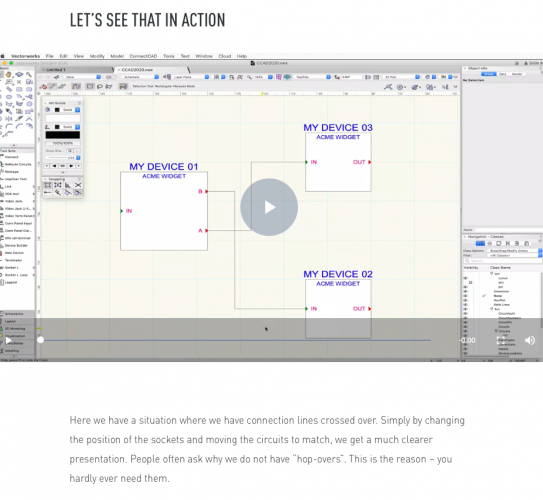
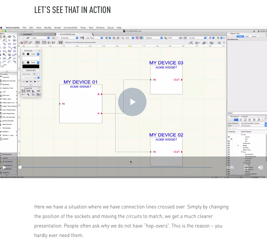
EDIT* I ran across this information saying there was no way to do "hop-overs" in the documentation, completely missed the actual hop over tool.
-
Thanks for the info Conrad, I am using 2020.
This was the file I was looking for, I was able to add the items I needed to the list.
-
Hello,
I purchase ConnectCAD before it was fully integrated with Vectorworks, during my demo someone showed me how to add custom fields to Signal and Conn(on cable), but I do not remember how to do it. Does anyone know where I can edit this list? I am trying to add power to these lists so we can show PDUs and other power related devices in our single line drawings.
Thanks
Speaker Object Dispersion Line Weight
in Entertainment
Posted
Thank you for the reply, this is exactly what I am seeing. I have been able to change the line weight, but it is the pattern of the line that is the issue when exporting. If it is hardcoded it sounds like it is what it is.