All Activity
- Past hour
-
In the function list in Vectorworks there are the commands CE_TransformVector and CE_invTransformVector. They appear to be meant to transform a vector using a matrix (Matrix multiplication). It also says it requires the Handle of the transformation matrix (But I don't know how I can get the handle of a matrix). Has anybody ever used these commands? I can't find anything about them online. I think this might be quite a useful feature if it would be working somehow.
-
Thanks, duly noted. This is generally working pretty well. I've added a popup parameter to choose the number of colours required from one to three, which creates the same number of named classes to assign colours to, and the same number of colour cells in the tag. Only downside over a data tag is that a new position value in the truss won't trigger an update of the tag. I guess that is where things move in to event enabled, so I'll come back to that. Also, is there a way to force single-click insertion rather than click position > set rotation please? No big deal if not.
-
It's bright green in all 3D views. Custom, orthagonal, etc etc.
- Today
-
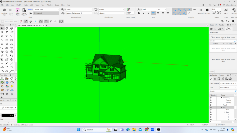
@aclymer Welcome to the forum. I'm assuming that you must be in a perspective mode in 3D? If you look at the top left of the VW window there will be a pulldown for view that will say something like Custom View or Right Isometric. Just below that is a view menu pull down perspectives. Yours probably says Narrow, Normal, or Wide Perspective (?). If that's the case the green you are seeing is the default "ground" for perspective views. To test this try setting the the view from a Perspective view to an Orthogonal view. If this makes the green go away then that the issue. You can either work in Orthogonal view or change the color of the ground in perspective views. To change the color of the ground in perspective views: Vectorworks > Preferences > Interactive Click on Interactive Appearance Settings… If you are sorting ascending by Interface Element then General - Background - Perspective Horizon Ground will be about the 7th from the top. There are color pickers on the right side to change the colors. If that's not it, take a screen shot and post it here.
-
 MBarahona joined the community
 -
I just got Vectorworks Architect 2024 today. When I go into 3D, the entire work area of the screen is bright green! I cannot find a way do turn this off. If you hold down the ctrl button and the mouse wheel to fly around, it briefly turns off. But when you let go, it goes right back to florescent green. My eyes can't take this. Can anyone help me turn this feature off?
-
Convert to 2022.zip
-
@Andrew Lees This is what I've found to make point clouds from Nomad work successfully. 1. Use a recent, pro version of the iPhone to get better LIDAR. 2. Smaller scans. Only do one room at a time. Maybe two if they are small. The issue is drift. The larger the area of scan the more likely that it will "drift" a little. That's why you are seeing some walls duplicated on a different axis. 3. I like to scan around the other side of connecting wall openings to get wall thickness and to help line up adjacent scans. It's important to always have objects or architectural features that will appear in at least one other scan to help line them up later. 4. Watch the screen as you are scanning. There is a slider on the bottom of the screen. It only controls pass through from the camera to the screen while scanning. It has nothing to do with what gets recorded (AFAIK). Try turning it way down so you are seeing primarily or only the points that are being recorded. Sometimes you will see a "jump" happen while recording. I can't prove it but I think that's the scan losing its place. Discard that scan and start over. 5. In the VW drawing, lay out all the rooms from individual scans. It takes a little while to rotate them all to the same direction. I've found that if you use the _VW.pts version of the file, the floors will be level, but not necessarily at Z=0. But they appear to be close to the same - usually negative - Z value. If you've got one scan of a hallway, then it's easier to align the scans of the rooms off the hallway using the door openings. If you keep each scan on a separate layer it makes it easier to work with and you are less likely to select the wrong scan by accident. 7. When you have all your room scans laid out, use the clip cube to cut the top and bottom so you only have a sliver showing about 3 or 4 feet above the floor. Try looking at it in top/plan view as well as top view in shaded rendering to see what shows up better for you. That will give you a floor plan that looks like all the wall lines are about 5/8" thick. You sort of have to draw it not too zoomed in. The closer you get the more you see the spaces between the points. You will quickly find the sweet spot. 8. Once you draw your walls, guess at window and door sizes and locations. Select one wall, turn on the clip cube and set the visibility to wireframe. Now it's really fast to use the new drag handles on doors and windows align them with then scans. 9. It also works outside. I've had pretty good success using it to get eave overhangs, roof pitches, hardscapes, external columns, existing tree sizes and locations. About half the time on a building the size you are working on it will hold together long enough to scan the exterior of the entire residence well enough to get an accurate footprint. I haven't tried this yet, but I've heard that using a tripod for your iPhone that rotates around 360 and scanning several times in the same room produces better results.
-
 aclymer joined the community
 -
But now the issue started again, crashing sometimes when sending to printer. Arg!
-
Hi all! Is someone able to help convert a VW2024 file to VW2022? I have attach it to this thread. Thanks! Archive.zip
-
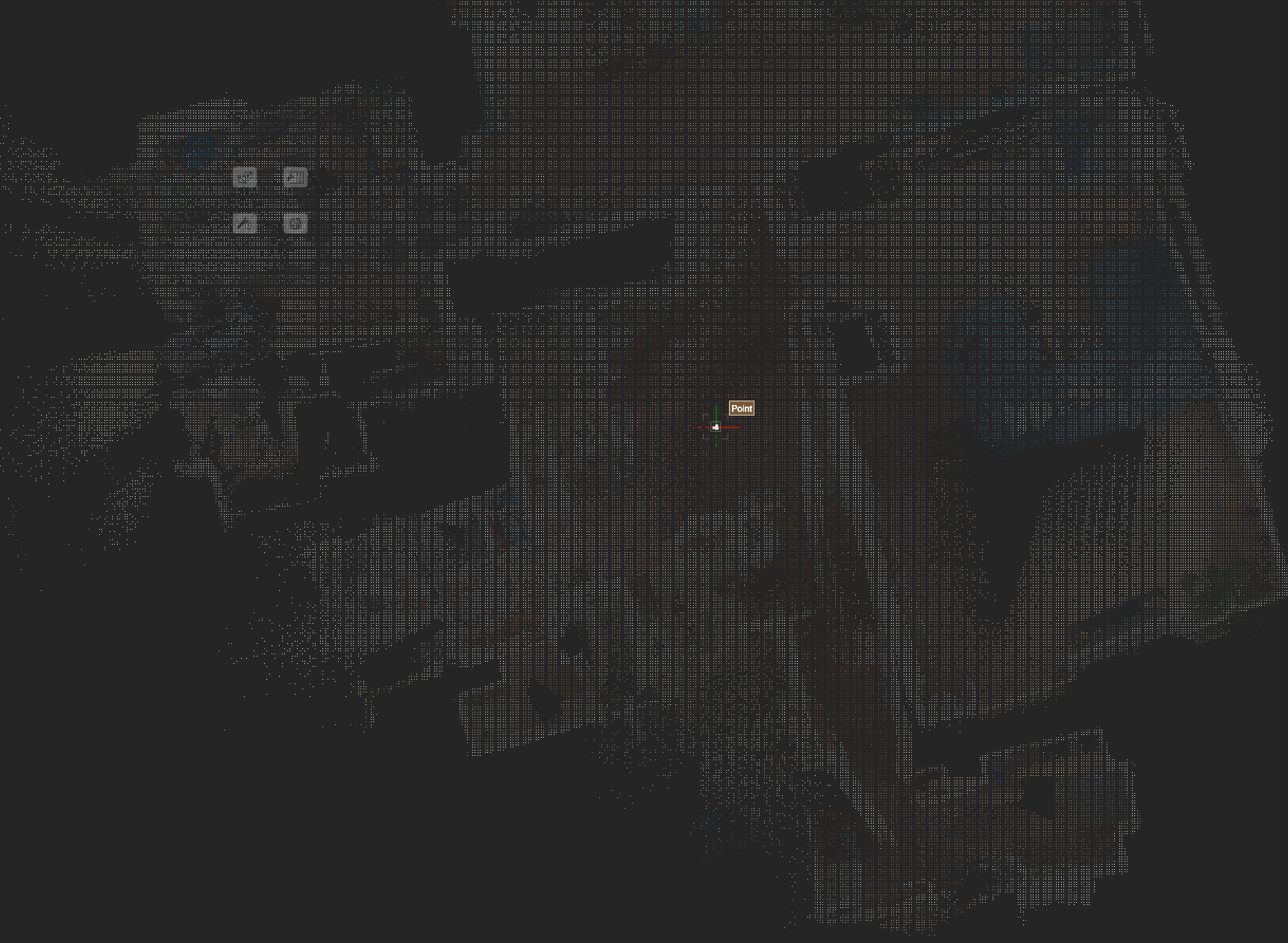
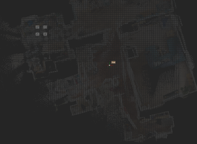
I am new to Vectorworks and this is my first attempt to use point clouds captured with Nomad. Now, my scan of this floor plan seems to be a bit of mash-up, but that is not my main issue right now. I have seen a VW video on this (https://www.youtube.com/watch?v=_cQv1da242Q) and the point cloud model shown in that seems to behave somewhat differently than mine. In the video the presenter is able to zoom in and trace the point cloud - which looks great. When I zoom in however I get two problems: The density of the point cloud seems to decrease - to the point of it being too vague to find hard edges to trace once I get close. I have a grid pattern superimposed over my point cloud. The size of this grid (which is manifest as gaps in the point cloud) gets denser and more obscuring the more I zoom in. The attached images show progressive zoom-ins as described above. This is an orthogonal top view (not plan view) with section box cutting the horizontal slice. For info, the point cloud was imported at 100% points resolution. Suggestions? Thanks


-
 Goodguyben joined the community
 -
 damianpaints joined the community
 -
Not really. 10 years ago I put 4 lights on separate circuits, 3 of which had the same unit number but different positions, on the same channel to make a path. Happens rarely, but does happen. Position and Unit Number would be unique, and would have the additional advantage of telling you where the fixture is. That doesn't matter with this problem, but the use of channel numbers to identify fixtures drives me crazy. Where the #$@&! is channel 203? It's not coming on, and the programmer wants me to troubleshoot it.
-

New transform mode in the selection tool in 2024 Update 4.
Tom W. replied to tomtomtomtom's topic in General Discussion
I don't think so but be interested to know if this kind of thing is scriptable. This kind of relates I think to what I posted about here i.e. being able to more easily switch between the fourth + whatever other mode of the Selection Tool you use rather than having to toggle through all four modes: It would be great to just be able to toggle Transform Mode on + off. -

Problem with controlling wall texture by class in VW 2024
billtheia replied to EliM's question in Troubleshooting
I am having the same problem. Would be great if VW2024 allowed mapping of class-assigned textures, as previous VW versions have done. -
I'm experiencing the same thing. Would love an answer to this question.
-
I sense a disturbance in the Force
-
 JFlagg joined the community
 -
The VW AI Visualizer is in its early stages, I would expect it to be behind the more developed user interfaces like Midjourney. I am sure we will see VW open up more control options in future releases. (I'd love to see support for training an LoRA with our companies existing renderings, sketch style, etc.) In the mean time, you may want to look into the the more open source solutions. Automatic1111, ComfyUI, and Invoke all offer stand alone packages you can run on your local machine, with a daunting set of control options and incredibly powerful customizations. I like InvokeAI, it is free to use and has a mission to create tools for creatives, not just the general masses. Of course, you have to have a pretty strong graphics card to do all of this on your local machine. Bart
-

New transform mode in the selection tool in 2024 Update 4.
cberg replied to tomtomtomtom's topic in General Discussion
Is there a way to set a keyboard command to activate the transform mode? (preferable to toggle). I know that U toggles between the different mode groups. But it would be nice to activate it directly somehow. -
I do find that AI can have a great sense of humor. Here is my favorite image from a prompt about clean water in the bathroom

-
 Andrew Lees joined the community
 -
 Because Vectorworks made that particular texture and hatch. I guess the person who made it must not have been paying close attention to the details, you see that from time to time in the Vectorworks library. You can make them match perfectly with the right hatch design.
 -
Vectorworks does export the alpha channel though...
-
 VjiupsMab joined the community
 -
Quite right that the Control Point is going to be based off of the PIO insertion point, and you did exactly the right thing to compensate for that. As a gentle warning, also make sure that your plug-in still works if the user origin doesn't match the internal origin. Nearly every VS function references the internal origin, so things can get screwy especially if you're using a plug-in that's saving coordinates into a text field. In those cases, you will need to use GetOriginInDocUnits to pull the user origin to compensate.
-
Working: def PickTest(): linkedPos = 'Unlinked' bool, objName, objHd, recHd, wallHd = vs.GetCustomObjectInfo() if objName: x, y = vs.GetSymLoc(objHd) pointx = vs.PControlPoint01X + x pointy = vs.PControlPoint01Y + y point = (pointx, pointy) pickHd= '' #FindObjAtPt Process container = vs.Handle() list = vs.FindObjAtPt_Create(container, 1, 0, pointx, pointy, 100) count = vs.FindObjAtPt_GetCount(list) for i in range(count): pickHd = vs.FindObjAtPt_GetObj(list, i) vs.FindObjAtPt_Delete(list) #If a handle was found and if it's Truss if pickHd and vs.GetObjectVariableInt(pickHd, 1165) == 641: if(vs.GetRField(pickHd,'TrussItem','PositionName') != linkedPos): linkedPos=vs.GetRField(pickHd,'TrussItem','PositionName') vs.SetRField(objHd,vs.GetName(recHd),'linkedPos',linkedPos) vs.ResetObject(objHd) vs.Locus(0,0) vs.CreateText(linkedPos) text=vs.LNewObj() vs.SetClassN(text, 'Lighting-Position-'+ str(linkedPos),False) vs.SetPenColorByClass(text) PickTest()
-
Hello @will2023, I believe you have submitted the file for the tech team to look into. We are working on the file and we will get back to you as soon as possible. Il update this thread with the resolution as well.
-
That did look promising, but looking at the function reference, there is a note of: Looks like VS:FindObjAtPt_Create, VS:FindObjAtPt_GetObj might be an option that supports a radius, which I will try, although the function doesn't seem to trigger intellisense which doesn't seem a good sign.
-
Maybe also look at ForEachObjectAtPoint which allows you to specify a radius rather than needing an absolute point. But I think you are correct about having to pass world coordinates not PIO coordinates.