All Activity
- Past hour
-
I love it! Thank you
-
AFAIR there was an option to "embed" DWG References when importing in advanced settings (?) Not sure if it is always the best solution to bring all references into the import file.
-
I have one door in my project where the data from the record is not displaying. The only difference in this door and all the others is the "Wall Closure" tab seems to be disabled. I have no clue why this is or why it would make a difference. I am attaching a lot of screen shots to illustrate wjhat I am seeing.Door on Plan.pdfDoor Schedule.pdfDoor in Design Layer.pdfDoor Information Pallet.pdfWall closure settiings for wall.pdf
-
@MullinRJ - that's amazing. I think vectors are very powerful but I have a hard time getting my brain wrapped around them. I think because they looks so similar (Pt.x, Pt.y, and Vec.x,Vec.y) I have a hard time understanding how I use them differently. Is there a good place to help me understand vectors better? Dave
-
 rethwik joined the community
 -
That sounds like an exciting project!
-
I'm just getting started on 3d after a long time using only 2d. Are the slab setting under organization/stories referring to the same slab as drawn with the slab tool? For example, I'm starting from the template file which has stories set up with 1' slabs, but the actual slab assembly will be something like 10 3/4". If not, should they not be referred to differently? Also, when I got to top and bottom bounding, which slab definition is it referring to? I'm getting a little confused.
-
@Tom W. On the bottom right set the height and width to 0 Window Custom.vwx
- Today
-
 I have a DWG from an architect and his files have a referenced as-built inside the design development file. So, when he sends me updates, he is only sending the design development. Do I have to reference each file in my working file, or is there a place for me to click on "show reference files inside reference files"? I have converted his files into vwx - and did reference his as-builts in the vwx of his development file - but maybe I should just ref both as-built and development separately into my working file?
 -
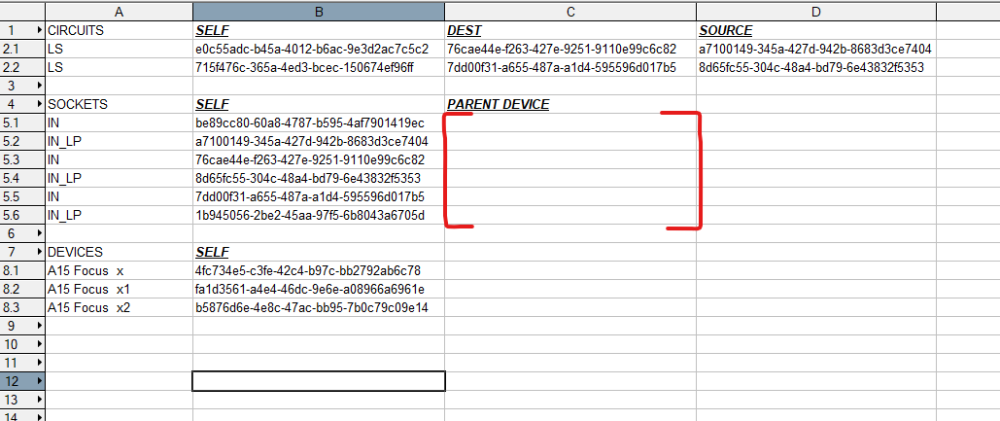
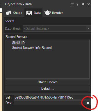
Hi @Nikolay Zhelyazkov, I've kept trying at this but I'm just stuck at what feels like the final hurdle. Could you have a quick look at this file please? There is a script and worksheet. It's all working except for sockets storing their parent device UUID: Once I've run the script and the worksheet is populated, I can edit a device and see that the field is by-instance, even though it's not set as that in the Data Manager. If I toggle that by-instance to calculated, it does show the Device UUID, and then recalculating the worksheet will show it. But that has to be done for every socket. Any ideas on how I can get it to go straight to calculated, please? ExportTesting2.vwx
-
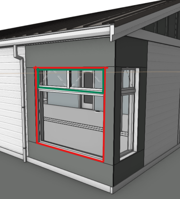
@JuanCarlos can you post the file? I don't understand how you combined the bottom two sashes into one... Or just explain it. Thanks!
-
Just reading this, I am wondering how support wants to distiguish between training needs and a real issue. For me it happend not only once that I was struggeling for solutions, thinking that I'm not on the right training level, when in the end I found that it was not a training issue but a bug. I really must say that my experience with local support is that all answers I got from them were terribly weak, in comparison to the answers I got here in this forum. Why not developing this forum further and put more personal strenght in here, instead of leaving this to local supportes that dont have the personal power for this ?
-
I think the poly is "consumed" during the creation of the slab. If you need to use the poly after the slab creation I think you need to duplicate the poly first. I am not certain if the "copy" or the "original" will be the one retaining the UUID. I think when you make a copy in VW, the copy is the one that ends up selected and the original is unselected. Or maybe it is the other way around.
-
I have noticed that in certain VW-documents the preview lines called with RunTempTool show at a wrong location, with an offset. The actual objects are implanted at the right location, and the variables used to compute the locations are also all correct. So there must be an issue with the temporary line functions themselves, vstDrawCoordLine vstDrawCoordArc etc. Has anybody experienced this? As of now Ive not been able to recreate whatever causes this to happen in some documents.
-
@CAD Cadet It is possible, it's just not the friendliest option! In the Window Tool General > Custom Configuration Options. But don't loose hope, we are working on it https://www.vectorworks.net/en-US/public-roadmap Window 2 top awnings.pdf
-
Hi all, I took the advice to use uuid to track elements. In most cases it works fine, but I observed something strange when using vs.CreateSlab(). Here is my code: vertices = [(1130,1570),(550,1570),(550,1280),(990,1280),(990,1130),(840,1130),(840,550),(1130,550)] vs.ClosePoly() vs.Poly(*vertices) # create polygone from vertices poly_h = vs.LNewObj() poly_uuid = vs.GetObjectUuid(poly_h) for i in range(5): poly_h = vs.GetObjectByUuid(poly_uuid) vs.AlrtDialog(f"handle iter:{i} " + str(poly_h)) # poly_h is always 0 after 1st iteration, with the same uuid it cant find the corresponding handle hslab = vs.CreateSlab(poly_h) poly_uuid = vs.GetObjectUuid(poly_h) vs.AlrtDialog(f"uuid iter:{i} " + str(poly_uuid)) # the poly_uuid matches the initial one in the first iteration It looks like after passing the polygon's handle to the CreateSlab function, the handle re-found using its corresponding uuid will always be 0 (None). Not sure if this is a bug. Any ideas about how to track the polygon using uuid after the create slab operation?
-
Hello @T_Lichterman what worflows are you using image generation for? We will be continuing to hook up the Vectorworks AI Visualizer into relevant user workflows over time. Also note that Veras plugin for Vectorworks is now available, check that out as an option:
- 1 reply
-
- 1
-

-
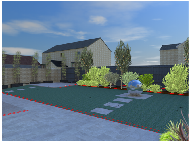
Recently, when I have rendered a 3D illustration the image shows red lines in odd places. When I wish to present to a client I export the best image into photoshop so I am not sure whether it is me, VW or PS.
-
Attached find what I did for similar situation for a portable building. It uses two window objects, one inserted in the wall and one as a group. Stacked Window.vwx
-
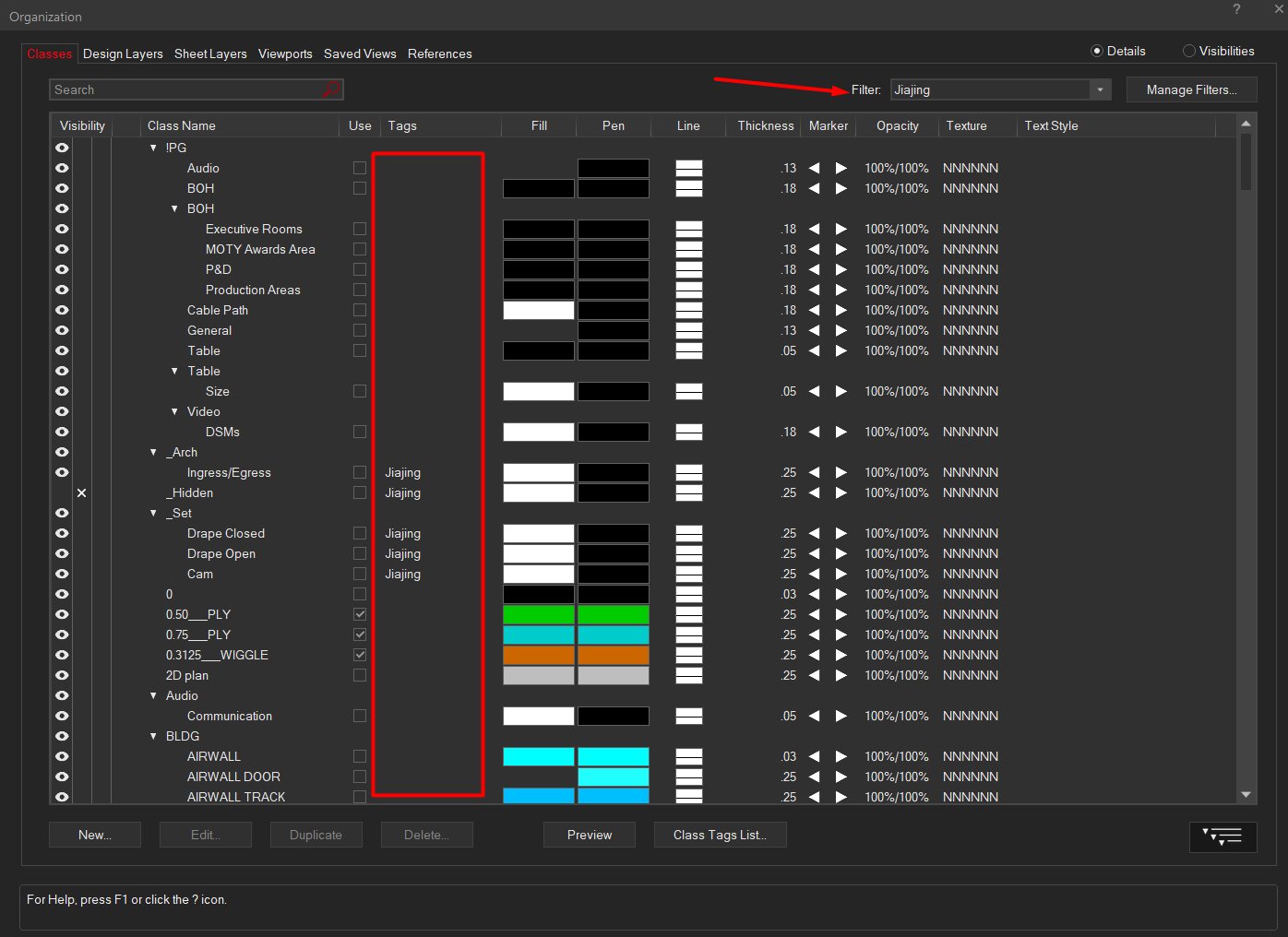
I have filter set for classes in organization dialogue , I do not think it is actually working. It works fine on elsewhere

-
Hi Cody, Thanks for your input - I've been remaking the model whilst watching this webinar, i'm getting much closer to what I would like and learning about some of the best practices VW recommend. In true VW fashion there are some baffling things that make things much harder. I didin't know that new Site Modifiers brought in in 2023 only work on the "Proposed" site model view. VW doesn't tell you this if you use them though!
-
Hi, I've annotated and dimensioned some drawings on my sheet layer - I entered into the viewport to do so as I was told this would help when changing the scale of my drawing. However, My drawings are 1:50 and when I try changing them to 1:100 all the dimensions are bunched up... Is there a way that I don't have to re-annotate the drawings and just have my dims/ text rescale automatically? Many thanks in advance
-
 EvolveLAB Joins the Vectorworks Partner Network, Delivering an Additional AI Visualization Resource to Designers. Global design and BIM software provider Vectorworks, Inc., part of the Nemetschek Group, has welcomed data-driven app developer EvolveLAB to its Partner Network to provide customers direct access to AI-powered visualization app Veras. Bringing a mature AI technology fine-tuned for high-quality visuals straight into Vectorworks; this seamless integration allows customers to enhance their creative workflows, gain efficiency using predefined prompts, and perfectly balance AI flexibility and precision in creating impactful visuals. The Veras integration joins Vectorworks’ recently released AI Visualizer and will provide customers with additional options to harness AI's potential, specifically for visualization. Vectorworks Architect, Landmark, Spotlight, and Fundamentals professional license customers will benefit from the added ability to explore AI iterative designs and to create visuals of their 3D models, even in the earliest stages of their design process. “We are excited to partner with the EvolveLAB team to bring Veras and its trusted capabilities to Vectorworks users,” said Vectorworks Senior Director of Rendering and Research Dave Donley. “This collaboration underscores our dedication to empowering designers with cutting-edge tools that not only enhance their creativity but also boost their efficiency. Acting as a complement to our AI Visualizer, the integration of Veras enriches our customers’ toolkits, offering them unparalleled flexibility, speed, and the capability to vividly visualize and seamlessly share their unique design visions with the world.” The integration introduces a new web palette within Vectorworks, enabling the creation of high-quality project imagery based on a 3D model and natural language or predefined prompts. Customers can refine and iterate imagery from previously created images and generate up to four images simultaneously, streamlining the visualization process. “We are honored to bring additional AI ideation and rendering to the Vectorworks community by incorporating Veras into its software,” said EvolveLAB President Bill Allen. “From this partnership, we look forward to the tremendous value it will add to an already amazing application.” Customers can explore Veras' capabilities by installing the Veras plugin using the“Install Partner Product” command from the Vectorworks Help Menu. To stay in the loop on upcoming features, integrations, and plugins, visit the Public Roadmap.
-
The old way is one of my most missed features from previous versions of VW. I used it all the time.
-
 @DomC, Yes, screen plane planar objects into groups are showing correctly. I didn't notice that I was creating objects in the layer plane and only grouped objects disappeared in the packing… So it is sufficient to change the Dup in container node like this (just the part between my comments) : #Dom @Marionette.NodeDefinition class Params(metaclass = Marionette.OrderedClass): By = 'DomC';import datetime; now = datetime.datetime.now(); y80f5 = now.year;m80f5 = now.month; d80f5 = now.day; h180f5 = now.hour; mi180f5 = now.minute; s180f5 = now.second; ms180f5 = now.microsecond; h2 = now.hour-12 if now.hour >=13 else now.hour; VersionChange1 = str(y80f5)+' '+str(m80f5)+' '+str(d80f5); VersionChange2 = str(y80f5)+'-'+str(m80f5)+'-'+str(d80f5)+'-'+str(h2)+'-'+str(mi180f5); this = Marionette.Node( "Dup in Container" ) this.SetDescription( 'Duplicates Objects in a Container or active Layer' ) object = Marionette.PortIn(vs.Handle(0), 'obj') object.SetDescription( "The input object" ) container = Marionette.PortIn(0) obj = Marionette.PortOut() obj.SetDescription( "The result object" ) def RunNode(self): l = vs.ActLayer() o = self.Params.object.value pioHandle = self.Params.container.value if pioHandle == 0: vs.Message('kein PlugIn') pioHandle = l created = vs.CreateDuplicateObject(o, pioHandle) #this part allows the groups displaying correctly if vs.GetTypeN(created) == 11: #read components in the group h = vs.FInGroup(created) while h != 0: vs.SetPlanarRef(h, 0) #set each object planar ref to top / plan h = vs.NextObj(h) #end of my added code self.Params.obj.value = created
 -
@MullinRJ Thanks for the help. I THINK I could have done this, but your explanation is so much clearer than mine would have been. And at the time, my brain would not tell me how to make the original vectors/points. Thanks for the refresher.