All Activity
- Past hour
-
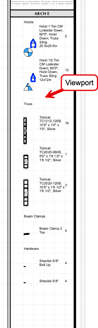
We are hunting a bug and this file helps. For now, I recommend placing a viewport of a summary key in your rigging design layer over the title block area. The Summary key is working as we wish in Design layers. Sorry, no; you can't place viewports inside the title block style. It'll have to sit over the title block on sheet layers for now.
-
I'm also having this issue, panic/crash doors have the hardware on the outside. Now if there its a fire, no one will be able to escape the room.
-
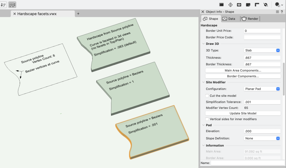
Ahhh! That's it!! @Tom W. - brilliant, as usual. For this Hardscape, the value defaulted to .083. Tried value of 1, which essentially eliminated all the curves and subbed in a single point. And decreasing values. .001 did the trick. The Edit Path window shows the orig source with the beziers intact. -B
- Today
-
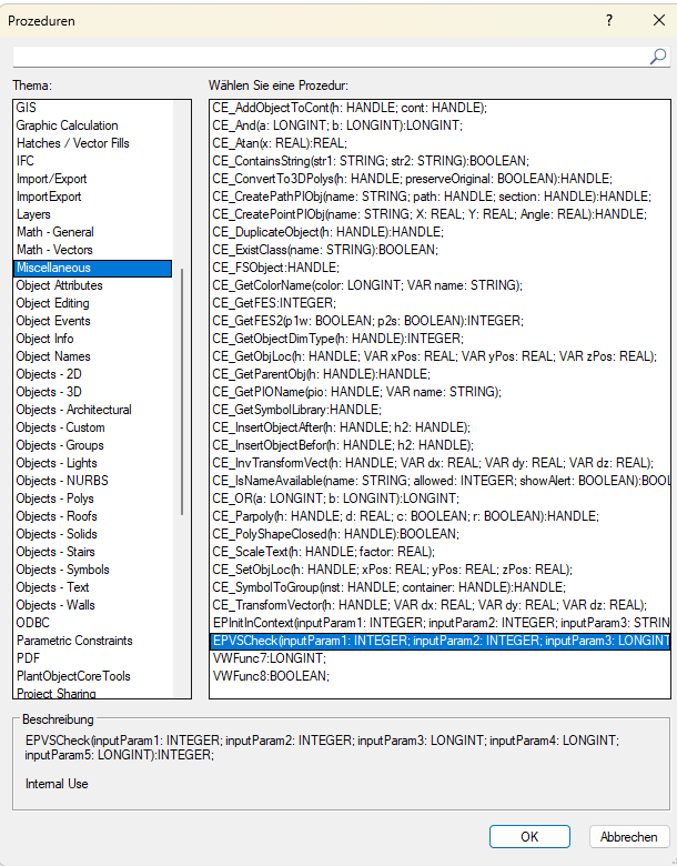
I think the correct way to go about this would be: PROCEDURE xxx; VAR dx, dy, dz :Real; BEGIN dx:= 2; dy:= 4; dz:= 6; CE_TransformVector(FSActLayer, dx, dy, dz); message(dx, dy, dz); SysBeep; END; Run(xxx); I think the function is supposed to take a coordinate and multiply it with a transformation matrix, the return values will be the new coordinate. However I have tried all kinds of objects, layers etc and the output values always remain the same. I don't know how to get a handle to the matrix. There is a bunch more functions in the category but none of them appear to work with matrices:
-
Also try objects on the Screen Plane vs objects on the Layer Plane. Raymond
-
@FMA, Assuming it does exist on your machine, why not try to use it to see what it does? 1) Draw an object. Start simple (line, rect, poly, text, etc.) and work your way up to more complicated objects (symbol, extrude, PIO, etc.) 2) Create a script. PROCEDURE xxx; VAR dx, dy, dz :Real; BEGIN CE_TransformVector(FSActLayer, 1, 1, 1); SysBeep; END; Run(xxx); 3) If it compiles, select one of your objects and run the script. 4) If it doesn't compile, try: PROCEDURE xxx; VAR dx, dy, dz :Real; V :Vector; BEGIN V := CE_TransformVector(FSActLayer, 1, 1, 1); Message(V); SysBeep; END; Run(xxx); 5) If you do get it to compile, try changing the constants for dx, dy, and dz and rerun the script to see what happens. Try (1,0,0), (1,1,0), (1,0,1), (2,1,1); (1,2,1); (1,1,2); etc. 6) Write back if you find anything interesting. Raymond
-
Yeah, I can get it to work but I have no idea what the matrix handle is supposed to be. Maybe it's just for internal use.
-
 ei4 joined the community
 -
That was my manual measuring experience so far too. I always hoped Lidar Scans would prevent this.
-
The command must be distributor specific. I just placed your command as you defined it in a simple script and got the following syntax error: Line #10: CE_TransformVector(H, dx, dy, dz); | { Error: Identifier not declared. } The same error appears in VW 2023 and 2024. Raymond
-

‼️ CONTENT REQUEST: L-Acoustics symbols
JustinVH replied to Mark Aceto's question in Wishlist - Feature and Content Requests
This content has been released on April 25, 2024 in the April 2024 Premium Library update in the English International version of VW2024. It is located in the Audio Bumpers and Audio Speakers folder of the Premium libraries. If you are using a localized version of Vectorworks is may take a little longer for your version to be updated with this new content. -
‼️ CONTENT REQUEST: L-Acoustics symbols
JustinVH replied to ZekeC's question in Wishlist - Feature and Content Requests
These symbols have been released on April 25, 2024 in the April 2024 Premium Library update in the English International version of VW2024. They are located in the Audio Bumpers folder of the Premium libraries. If you are using a localized version of Vectorworks is may take a little longer for your version to be updated with this new content. -
L Acoustics KS28-Bump Dual Subwoofer Bumper
JustinVH replied to gangotti's question in Wishlist - Feature and Content Requests
This symbol has been released on April 25, 2024 in the April 2024 Premium Library update in the English International version of VW2024. It is located in the Audio Bumpers folder of the Premium libraries. If you are using a localized version of Vectorworks is may take a little longer for your version to be updated with this new content. -
 In the past I have only really used VW in a 2D capacity, drawing interior elevations on design layers and then viewporting those 2D elevations onto sheet layers. I've always annotated and dimensioned in the design layer as well so that I can adjust elevations as needed while doing so. I am trying to learn a new workflow to create 3D floor plans and then use the create interior elevation viewport command to create the elevation "shell" automatically and add detailing on top of it....as I'm finding that a lot of detailing for millwork, cabinetry, finish carpentry etc. is drawn more efficiently (and better looking) in a 2D capacity (I also haven't found much straightforward training on this). From what I've read, this is generally done via viewport annotations for most people. Is it possible to reference the floor plan while detailing the elevation in order to draw in cabinetry etc. accurately as it's drawn in the floor plan? PS I cannot add a signature for some reason - am working on VW 2022 SP6 Any tips / workflow suggestions for interior design drawing are much appreciated!
 -
I have to ask this again, I thought I would get it to work but I still didn't. How is it possible to interrupt/get input during the RunTempTool Function? RunTempTool from the function reference: (This draws a simple temporary line and the function gets interrupted with the first mouse click, so far so good) PROCEDURE Test; VAR pt1, pt2 : POINT; FUNCTION TempToolCallback(action, msg1, msg2 : LONGINT) : LONGINT; VAR pt : POINT; BEGIN TempToolCallback := 0; CASE action OF 3: BEGIN {kOnToolDoSetupEventID} vstSetHelpString ( 'Just click once.' ); END; 103 : BEGIN {kToolDrawEventID} vstGetCurrPt2D( pt.x, pt.y ); vstDrawCoordLine( pt.x, pt.y, pt1.x, pt1.y ); END; END; END; BEGIN pt1.x := 0; pt1.y := 0; RunTempTool( TempToolCallback, FALSE ); END; RUN( Test ); But in the Function reference someone also wrote that: If toolCallback returns 0 it exits on first click, if it returns 1 it keeps gathering clicks. The thing is, if I set TempToolCallback:= 1, then the function will just go on for ever. I've tried setting TempToolCallback to 0 and that technically works, but in a very unreliable way. For example: PROCEDURE Test; VAR pt1, pt2 : POINT; key: LONGINT; bool: BOOLEAN; FUNCTION TempToolCallback(action, msg1, msg2 : LONGINT) : LONGINT; VAR pt : POINT; BEGIN TempToolCallback := 0; IF bool = FALSE THEN TempToolCallback := 1 ELSE TempToolCallback := 0; IF KeyDown(Key) = TRUE THEN bool:= TRUE; message(bool); CASE action OF 3: BEGIN {kOnToolDoSetupEventID} vstSetHelpString ( 'Just click once.' ); END; 103 : BEGIN {kToolDrawEventID} vstGetCurrPt2D( pt.x, pt.y ); vstDrawCoordLine( pt.x, pt.y, pt1.x, pt1.y ); END; END; END; BEGIN bool:= FALSE; pt1.x := 0; pt1.y := 0; RunTempTool( TempToolCallback, FALSE ); END; RUN( Test ); This will set the Callback to 0 when a key is pressed (Which will stop it at the next click) but the RunTempTool in VS only appear to be running when the mouse is moved. So the Key input can only be registered while the mouse is moving. Using IF MouseDown(X,Y) = TRUE THEN bool:= TRUE; is even more inconsistent (It is also very unintuitive for the user to move the mouse while for example clicking on a point). Getting Key input during a RunTempTool Function is also generally difficult when the Callback is just 0 and the function simply runs once (I believe that is, as I said, because the function only runs when mouse movement is detected). Has anybody got their head wrapped around this Function or found convenient ways to declare the callback, or found a work around? I've spent quite some time with it now and I would really like to get it. There also appears to be a dimension with the tool events to it that I don't fully understand (CASE action OF 3, 103 etc).
-
 Thanks! That works for Length. I thought that this will work for Size and Series as well but it doesn't. What's going on? is there a reference for such topics - for rainy weekends? Peter
 -
Weird problems in rendering are almost always caused by objects too far away from the origin. I said above that the number was 4km from the origin. Don't quote me on that. It might be 7km. I don't remember exactly.
-
I agree about room plan. It can get confused by soffits, vaulted ceilings, timber frame roof trusses, etc. With point clouds you can usually get a reasonable slope to a vaulted ceiling, number and approximate size of beams, placement of HVAC supplies, light switches, wall thickness, difference in elevation between floors, etc. Not perfect. But so so so much better than spending a day with two people and a tape measure.
-
I have to learn more about this... Can you expand on this CSV file that I cannot find anywhere? @spettitt
-
That did it! Thank you so much! I have no idea where those rectangles came from. Probably some mistaken value input somewhere. Thanks again.
-
🤣 6. Enjoy not spending an entire day measuring a building knowing that you will miss getting at least one (but probably more) critical measurements. Nomad point clouds aren't perfect, but they are way better than trying to read hand written measurements off of a crowded, incorrect old drawing two weeks after you measured the building 🙂
-
Not sure if really everything was colored .... but I once had to learn that a Heliodon sun color will adapt to the color of the Class the Heliodon is assigned. (When Attributes assigned by Class) I tend to assign bright Class Colors to non-architectural objects like cameras or lights, which I never use anywhere else. Pink and purple in my case. And suddenly all my renderings were pink and it took me a few days to realize the cause.
-
How to draw (lines or walls) parallel to another on the fly?
zoomer replied to MarCur's topic in General Discussion
"T" key is the official general VW drawing support for your problem and the main intention of the "T" key. As I mostly have to deal with 90° perpendicular/rectilinear Walls only, I usually just misuse the "T" key to lock only to only a single X, Y or Z axis. Which was the only way to do so, until we got the 3D Giszmo, now even available for standard Selection/Drag Tool. But in VW there are often workarounds. Often by using Tools other than intended ... Or in this case, if I want to draw a Wall in the same arbitrary angle like another Wall .... I would just copy the initial Wall to the new point and adapt its dimensions, change its Wall Style if necessary or whatever needed - before I try to find the recommended way ... -
Apple macOS 14 Sonoma Compatibility - Feedback
Pat Stanford replied to JuanP's topic in News You Need
1. VW2022 is still completely compatible with everything that was available when it was shipped. 2. Blame Apple. They are the ones who have changed the OS in such a way as to break older software. -

DWG export creates blocks out of Hardscape and Landscape areas
Jeff Prince replied to TeeMuki's topic in Site Design
That's how it works currently. Symbols export as nested blocks. Hardscapes export as blocks composed of a hatch, a hatch polyline boundary, and an object polyline boundary... all of which is classed. You can get rid of the extra polyline boundary by deleting the objects on that class. Of course you need to be organized in Vectorworks in regards to how you use classes for this to be a quick and easy process. You probably want groups and symbols to convert to blocks. The first level of block is named "parametric object..." You can filter a selection set in AutoCAD for blocks named "Parametric object*" to select them all and then explode. Plant export first into containers named "parametric object...", once you explode them to their nested block, it is named after the plant. Most objects follow the same logic. So, exploding that first level container symbol is a one step process for you entire drawing. The next step in AutoCAD is to simply filter for objects the container class(es) for your hardscapes and delete that. You will then be left with an outline and hatch for your hardscapes. It's like a 2 minute process for the largest of drawings, when you have an organized class system in Vectorworks. -
So, I take it there are no plans to make Vectorworks 2022 compatible with Sonoma? Software is only 2 years old and no longer supported?