All Activity
- Past hour
-
 My pleasure. That was an interesting workflow to look at. You might want to look into using Textures that have hatches built in for hidden line rendering. That would save you so much time. Then, you could use staked viewports to combine Hidden Line and Shaded (or any colored rendering mode) to create dramatic effects. Here are two extruded rectangles with one texture assigned to each. Note how the Hidden Line rendering shows a line hatch and the Shaded rendering shows a texture. This is so much easier to manage than making those 2D polys and assigning hatches, especially when changes occur. Here is the same technique applied to your project: The CMU and Glass block textures used here are built into Vectorworks, but you could make your own too.... The same scene in Hidden Line Rendering, note the hatches are generated from the hatch built into the Texture applied to a single object. No need to make those 2D Polys anymore 🙂. You would just need to make textures with associated hatches and make sure they are sized correctly. Things would get fast and easy from there.
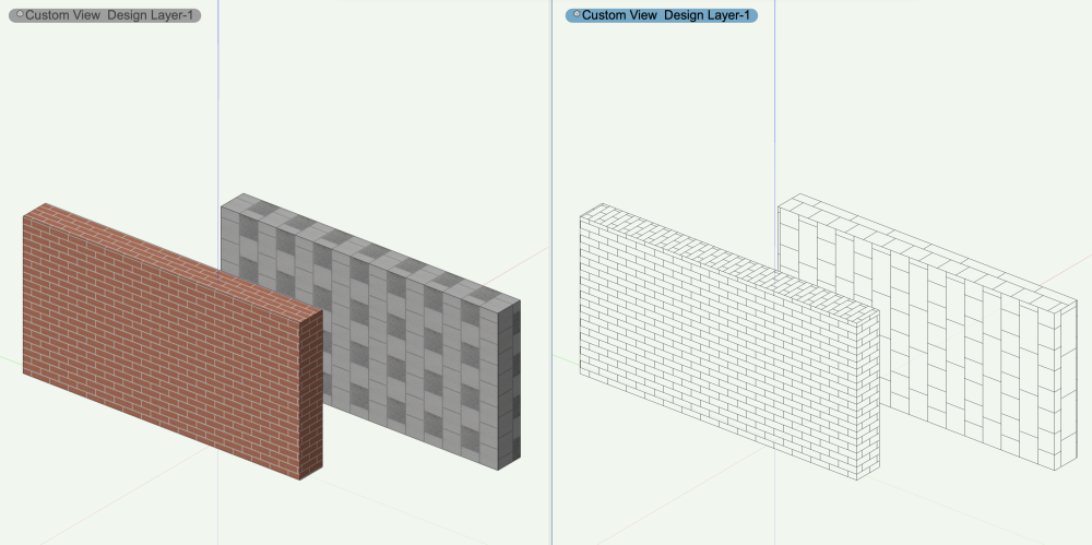
- Today
-
any chance @JustinVH can share the file with me as well
-
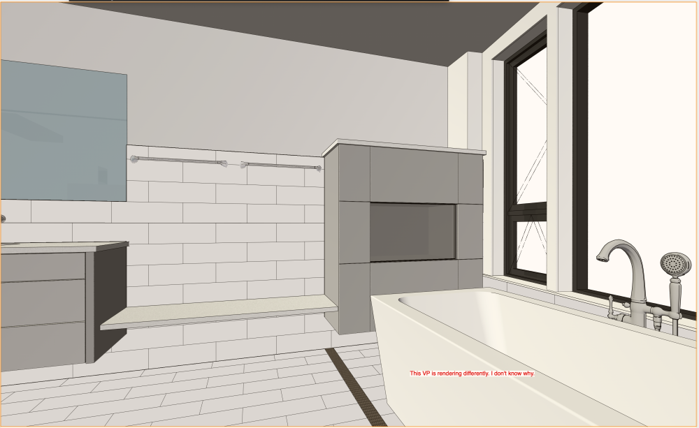
 @Jeff Prince Thank you! Those renderings are now good enough to send to the homeowner for comment. The fact that the one camera was coincident with the wall geometry is a humorous stroke of bad luck. I don't consciously use cameras to set up these views. I navigate to where I want to look using my Space Navigator (more recently called Space Mouse from 3D Connexions), and then choose Create Viewport. Now I see that I can click on Edit Camera from the VP to make adjustments. I appreciate your time and help! Ed
 -

Application Window - Please fix
rDesign replied to gplumb's question in Wishlist - Feature and Content Requests
Note that if you really want to 'cast your vote' for this wish-list item, you should click the 'up arrow' to the left of the Topic Title at the top of the page (screen cap attached below). As of right now this request has Zero votes.
-

Hoist Plug In Object - Add Text Linked to record to 2D component
lombargm posted a question in Troubleshooting
I am trying to get the hoist ID from the hoist tool to show up automatically at the center of my hoist symbol in 2D without having to turn on the label and move it to the center. I linked text to the Equipment Record that looks at the unit number (essentially the Hoist ID) correctly but the string I get back is a #text with no result. Any fixes? Hoist ID 2D.vwx -

Application Window - Please fix
mrpommer replied to gplumb's question in Wishlist - Feature and Content Requests
Cast my vote (along with 20-odd others here) for correcting this "design decision". This is one of the most irritating things about 2024 (which otherwise seems to have so much improved UI). Sigh. -
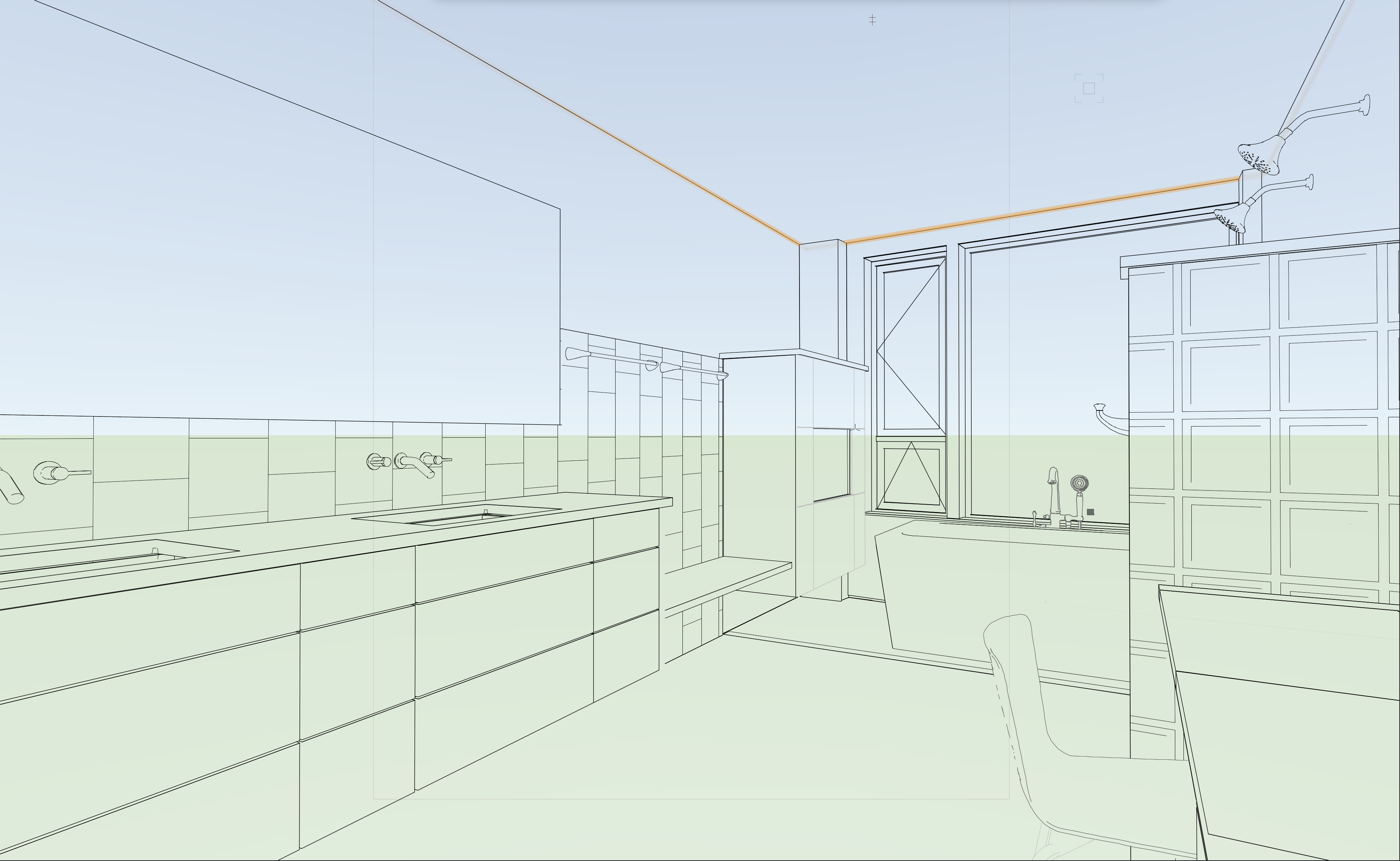
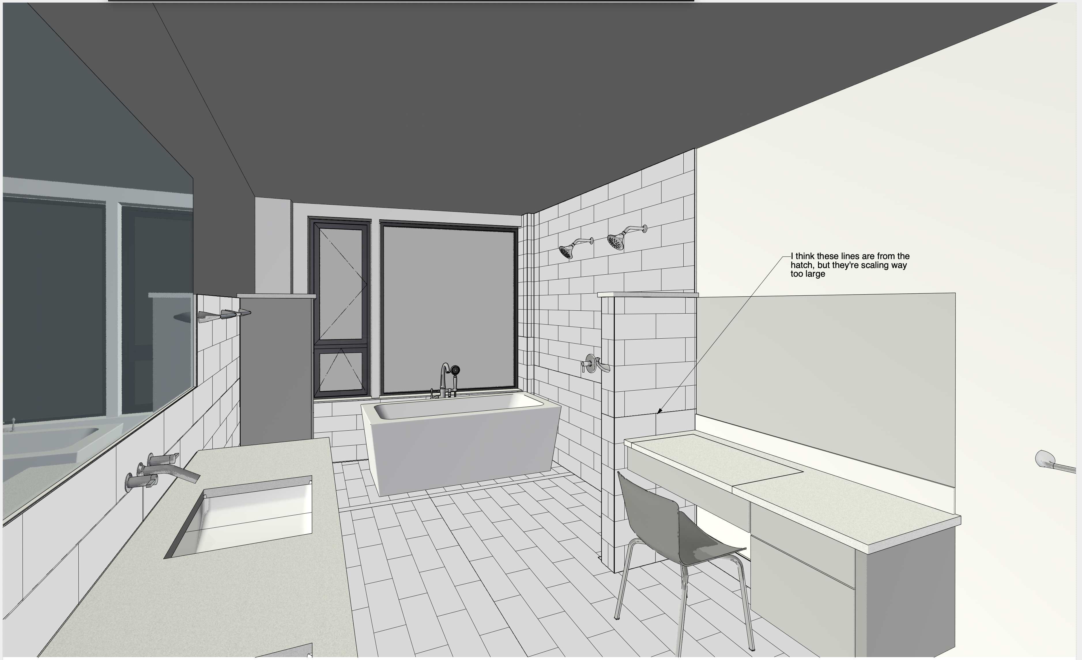
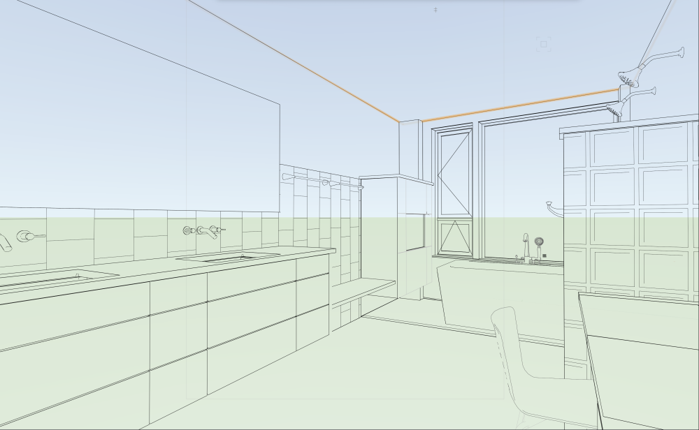
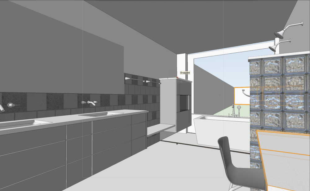
If you want the same results between different viewports, you have to use the same settings for the Layers, Classes, Rendering and Lighting settings. Sheet B4 is not using Foreground Render = Hidden Line, so your hatches don't show up. Once you fix that, your Advanced Properties are not set to Black and White only on this viewport, so you get colored lines. Correct that and sheet B4 is great. Sheet B3's camera position is coincidental with the wall behind the camera, which is incredibly bad luck and amazing that it occurred in such a way for the graphics to display this way. You can remedy this by adjusting your view.... or Pro Tip - put the coincidental geometry on a different Design Layer and then turn it off in this viewport. Think movie set when it comes to rendering these tight interior spaces, just remove some walls 🙂. Just remember, if you do that latter, make sure you turn that design layer on where it may be needed in other viewports. Clip cube in future versions of the software might be helpful, I don't think it works in 2021 the same as later releases. Fixed by hiding the "Wall Behind the Camera"
-
 Hi, I export a png rendering from Vectorworks 2023 with a transparent alpha channel. When I open it in photoshop and place it over a black gradient background. I can see jagged edges around the image. Does anyone know how to fix this? Thanks
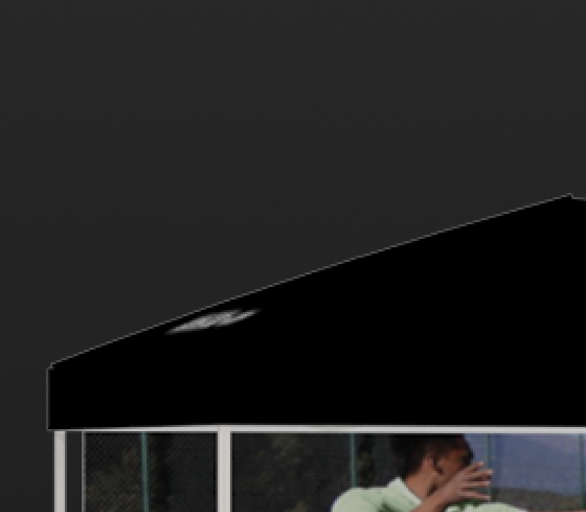
-
lombargm joined the community
-
This post from 2023 might help you get started on a basic way of pulling your truss info using PickObject. The code is in Vectorscript but it is very basic and should be easily translated to Python: In terms of building associations like what you're looking for, the AddAssociation functions don't quite work the way you might want them to. At the moment, the only options you have is to delete or reset your object if the associated object is deleted. There's not currently a way to have a an associated PIO update itself if the associated object has been changed (such as trim height in your case), so I always add a "Refresh Object" button to the OIP or write a menu command to refresh all of the desired PIOs in the drawing. The good news is that AddAssociation does not require the PIO to be event enabled. The bad news is that if you want to add buttons to the OIP, the PIO must be event enabled. I wrote up something of a "basic" event enabled plug-in with everything commented in case you would like to learn event handling. @FranAJA even adapted some of the code into Python, so you might find it useful: If you wanted to keep your PIO simple, what you might consider doing is using PickObject similar to my example above to pull the UUID of the truss object, then having a boolean parameter called "Lock" that would disable the PickObject code and keep the PIO associated with whatever object it last picked up with PickObject. OR you could get fancy by using a Control Point parameter and have the PickObject use the Control Point to pull the handle, so that the label can be wherever and the invisible control point just needs to be in contact with the truss.
-
 vdH_83 joined the community
 -
 Klisty joined the community
 -
Hello, my renderworks texture option is not there when I try to make a new resource.
-
I just tried this in VW2023 and it worked as expected. Can you post a screenshot of the filter parameters?
-
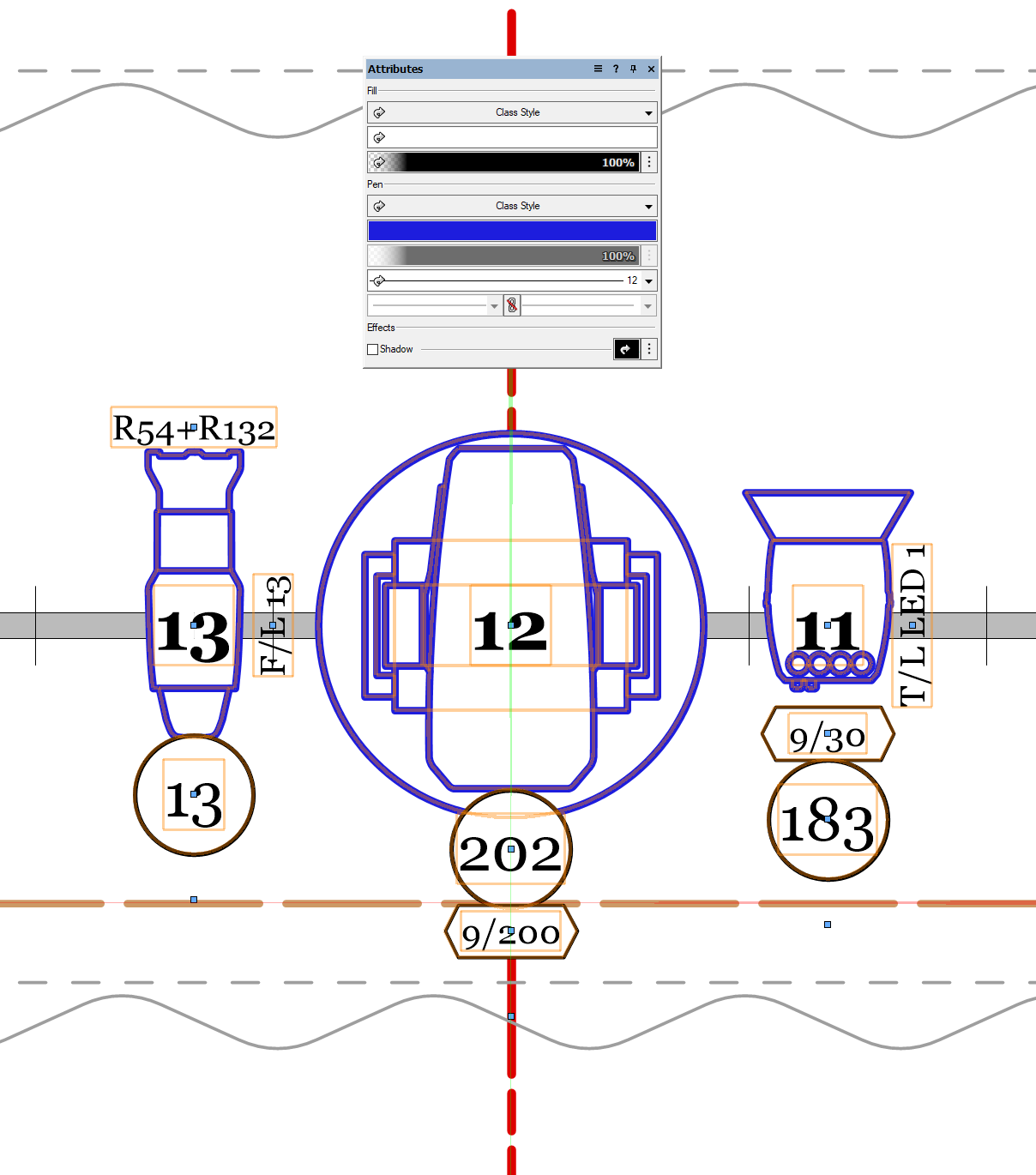
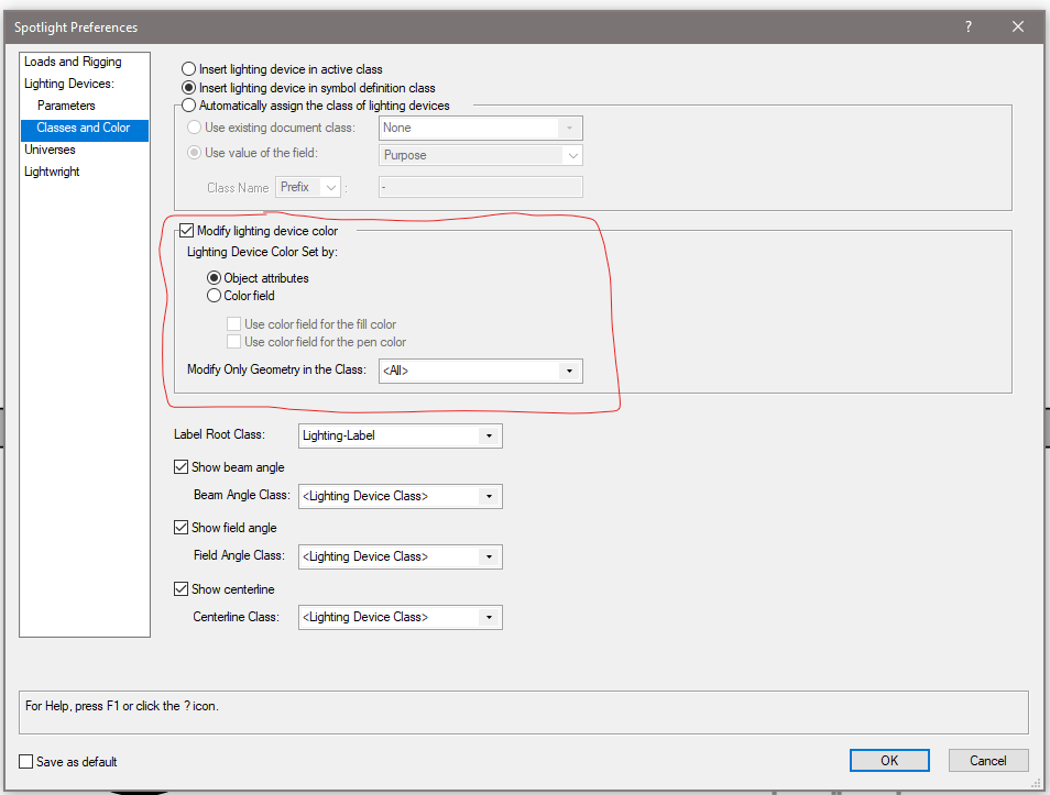
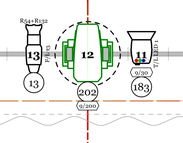
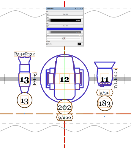
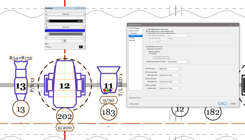
For lighting fixtures, there are a couple of different options you want to look into. These are document settings, so they will need to adjusted from drawing to drawing. They can be found under File - Document Settings - Spotlight Preferences. There is a tab within the Lighting Devices section called Classes and Color. These settings determine which classes new lights are placed in, and how color works for them. By default, Insert lighting devices in active class will be selected, so placing new fixtures will always appear in the currently active class. There is another option, called Insert lighting device in symbol definition class. This is my preferred method, and new fixtures would be placed based on the class specified in the Edit Symbol Options dialog for the symbol that defines the Lighting Device object. I prefer this because I can specify different fixture type be different classes if I so choose, and then I don't have to worry about what my currently active class while I'm plotting. So if I'm plotting out focus areas while I'm building my plot, I can leave my Focus Areas class active and know that my lights will always be in the classes I want them in. You can also have Vectorworks build classes for you based on a field parameter, such as color or device type by selecting the third option, Automatically assign the class of the lighting devices and choosing the options that you want. Now, onto how Lighting Device objects respond to Attributes. By default, Lighting Devices will only show the graphic attributes of the symbol geometry. This means that if you wanted some of the fixtures to be lined in blue and some in black, you would need two different symbols. However, if you check the box for Modify lighting device color, you will have a small bevy of options for how to handle the color. From the sound of it, you want to be sure to have Object attributes selected, where the lighting fixture will take on the values of the Attributes palette. But be aware that if you leave the Modify Only Geometry in the Class option set to <All>, this will affect all of the geometry of the fixture, which can lay havoc with things like moving light radius circles. Example of lighting fixtures based on symbol geometry: Same fixtures after selecting Modify Color - Object Attributes This means that if you want things to not be affected by this change, you would need to have elements of the symbol classed out so that it would only affect the desired geometry. Same example but with the Modify Only Geometry value set to my Lighting-Fixtures class You also have options to use the fixture's color field to set either the fill or pen of the fixture. One other place to look for something like this is using the Data Visualization tools. I can't help you too much with them, as they're not currently part of my workflow and I've only messed around with them a little bit, but there are some users of this forum doing some pretty amazing things to adjust things on a viewport by viewport basis.
-
Hello, I'm trying to set a recordfield of my .vso object. Normaly i just use vs.SetRField() but since this is a popup list i can't set the active value this way. Does anybody knows a workaround for this problem? Thanks in advance!
-

Door data not displaying in schedule
Dick Jenkins replied to Dick Jenkins's question in Troubleshooting
Thank you Tom. That was the problem. The stray door didn't have a door tag, but it had "on schedule" checked with D-01 as the number in the OI Pallet. The "M" in BIM has come really quickly with me but the "I" still eludes me. -
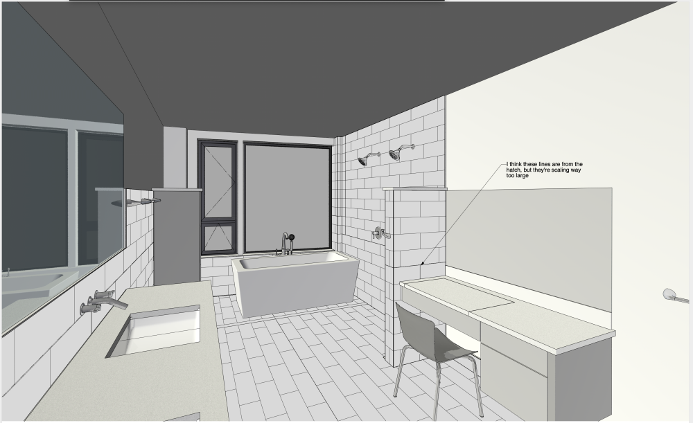
@Jeff Prince Thanks. The purged VW file is attached. I've also included a PDF showing what I'm getting from the VW file this morning. Now, only one of the VPs has the hatch scaling problem, and one has a new rendering problem. Previously, other VPs also had the hatch problem. I appreciate your attention to this TEST FILE w: polygons w: hatches vw2021.vwx Bath Perspectives w: hatch.pdf
-
@Jeff Prince Ooops! Yes, those are 2D polygons in 3D space. Regarding how they appear in VPs, now some VPs display them correctly; others do not. Is there a way for me to share the file with only you? I'd also like to eliminate our titleblock, or at least our stamp and signature, before I send our VW file, but I don't know how to eliminate the TB and VW won't allow me to delete the class that contains our stamp and signature. Ed
-
Is it possible you have two Doors in the file that share the 'D-01' ID number + the 'Mark' column is summarised...? (and the Doors have different parameters)
-
Hello! Using spotlight -> inventories I would like to be able to assign a lighting device to a source without creating an inventory. For my use case, I just want to make 4 simple sources and be able to freely apply any lighting device to any of them: Rental Purchase Props Scenic What do you think? Is this possible without creating inventories?
-
I love it! Thank you
-
AFAIR there was an option to "embed" DWG References when importing in advanced settings (?) Not sure if it is always the best solution to bring all references into the import file.
-
I have one door in my project where the data from the record is not displaying. The only difference in this door and all the others is the "Wall Closure" tab seems to be disabled. I have no clue why this is or why it would make a difference. I am attaching a lot of screen shots to illustrate wjhat I am seeing.Door on Plan.pdfDoor Schedule.pdfDoor in Design Layer.pdfDoor Information Pallet.pdfWall closure settiings for wall.pdf
-
@MullinRJ - that's amazing. I think vectors are very powerful but I have a hard time getting my brain wrapped around them. I think because they looks so similar (Pt.x, Pt.y, and Vec.x,Vec.y) I have a hard time understanding how I use them differently. Is there a good place to help me understand vectors better? Dave
-
 rethwik joined the community
 -
I'm just getting started on 3d after a long time using only 2d. Are the slab setting under organization/stories referring to the same slab as drawn with the slab tool? For example, I'm starting from the template file which has stories set up with 1' slabs, but the actual slab assembly will be something like 10 3/4". If not, should they not be referred to differently? Also, when I got to top and bottom bounding, which slab definition is it referring to? I'm getting a little confused.
-
@Tom W. On the bottom right set the height and width to 0 Window Custom.vwx
-
 I have a DWG from an architect and his files have a referenced as-built inside the design development file. So, when he sends me updates, he is only sending the design development. Do I have to reference each file in my working file, or is there a place for me to click on "show reference files inside reference files"? I have converted his files into vwx - and did reference his as-builts in the vwx of his development file - but maybe I should just ref both as-built and development separately into my working file?