All Activity
- Past hour
-

Framing Improvements
taoist replied to Taproot's question in Wishlist - Feature and Content Requests
Sketchup is not the only other software that will do roof trusses of various types. Vectorworks is way behind the curve with their framing tools. We should not have to "design" what we need. We amongst others are Builders, not just Designers. Love Vectorworks, but serious lacking in these areas. -
Content request - Decks coffee break
taoist replied to Cody Worthman's question in Wishlist - Feature and Content Requests
At some point in the past Trex DeckWorks software was available as a plugin. Do not know if it is still available. Vectorworks could use some serious updates to it's framing tools. Walls and floor framing especially. -
One addition to this is that there should be a preference to differentiate wood blocking which only gets a single slash \ though it, not an X. At least that’s the graphic standard that I was taught here in the US.
-

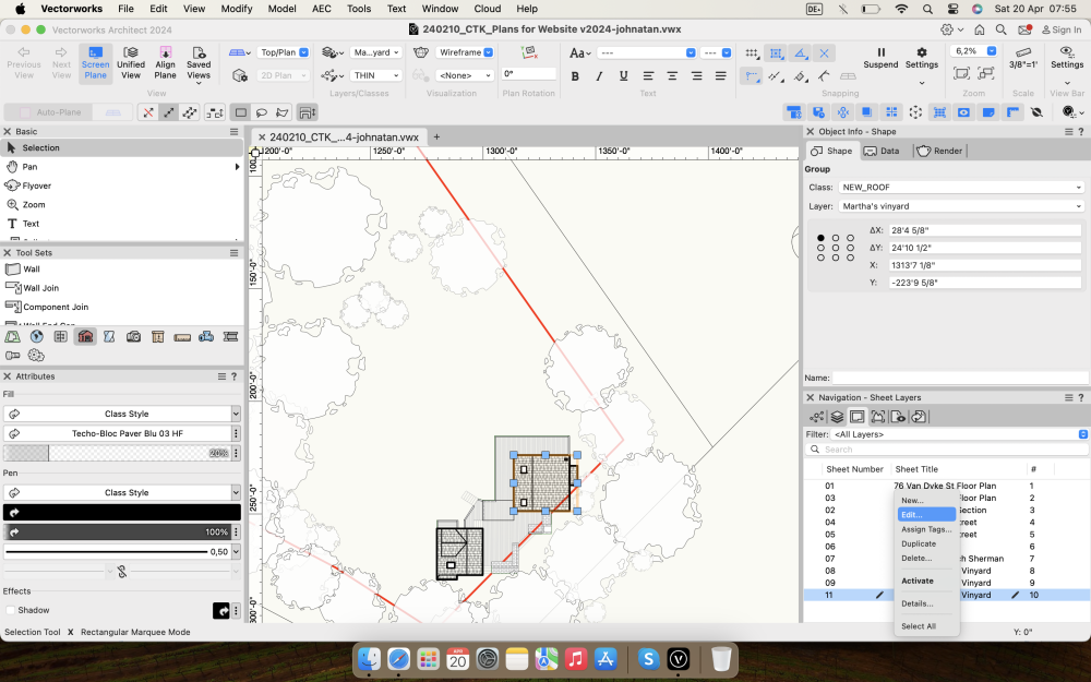
Candy cane stripe around Hardscape object
Cody Worthman replied to Cody Worthman's question in Troubleshooting
Not aligned either. Just a Hardscape slab with a pad modifier. -
Hello Raymond. Thank you very much for your reply, I really appreciate it! I will implement the changes you proposed, and maybe I'll find an intelligent way of sorting the input objects before I run the algorhythm in the future. Kind Regards.
- Today
-
 logan.duvall joined the community
 -
I'd like it to put an X on anything that I tell it is rough timber, whether it's a structural member or a generic solid or whatever. Ideally I'd tell it by assigning it to a class, or perhaps if I get around to adopting "materials" by that route instead. Maybe there's an argument it's a redundant drawing convention. It was more important when all drawings were black& white linework. Now, because plans are so often viewed digitally, I'm gradually becoming more relaxed about using colour to distinguish materials etc and I have a specific colour/texture for rough timber. Sorry, going off on a bit of a tangent there.
-
You could probably do something with WinDoor + the Use Symbol Geometry option... Create a symbol representing the two sets of vertical louvres with the lever in between then use the Window/Door Type called 'Symbol 3 Window'.
-
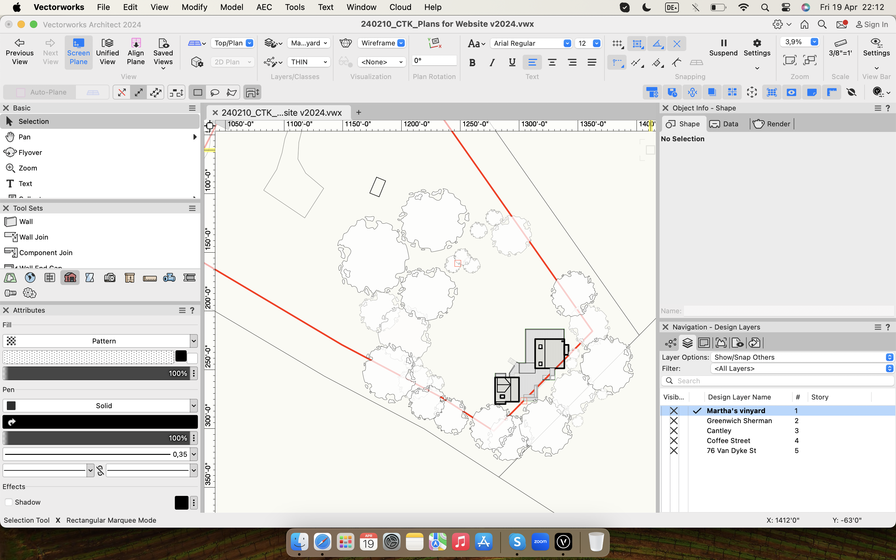
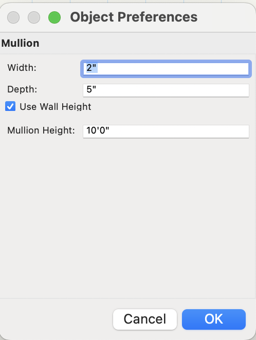
It drives me absolutely crazy that VW can't even draw an "X" in rough timber sections. This can't be a difficult feature to add to the framing member object. While we are at it, it is also mind-boggling that the wall framer command resorts to making geometry as 3D Solids instead of something parametric with top and bottom offset controls. Conceptually, framing as an overlay to the wall tool (which can be manipulated separately as needs arise but could be updated/ linked) makes a little more sense than trying to keep everything contained in the wall. To incrementally achieve fully framed walls, VW needs to develop a tool (or set of tools) that accomplishes framing. VW has a horizontal framing member but no vertical framing counterpart, which is inexplicable and tragic. The roadmap mentions "openings" as a new tool that will be developed, but the description is vague. Conceptually, openings could be a critical element in creating a framing vocabulary. (Horizontal members, Vertical Studs/Posts + Openings -- Think of the infinite BIM possibilities...) The mullion tool (which few people probably use) could form the basis for a "to be developed" Stud/Post Tool. The Stud/Post Tool should have a few profile shape options, like LG Metal Studs and 2 x sizes. There should be options for some connections and data regarding fasteners. Most importantly, the tool could integrate top/bottom offsets. Once developed, there should be a way to link the horizontal and vertical framing elements, like in the structural member tool. The problem is that VW is too "plan-focused," and all of this connection needs to happen in a vertical plane. Maybe create a wrapper of some sort to contain all the elements). Just some thoughts with only a half cup of coffee this morning.
-
@DCLD you have summoned me - well played. A few months ago I had the time to sit and finally crack the QuickTime Recording using Vectorscript, as most probably used in Animation Works, Solar Animation and Animation Pathing. Although I'm now using it for several more advanced animation and pathing tools in Vectorworks which are not yet released, I thought this particular thread deserved an update. @michaelk I've added to your (not so at all) badly coded rehash, and over-skinned my current/draft QuickTime code. Please find the attached file - however keep the following in mind; Combined Concept of Michael Klaers and James Russell 240420A - Multiple Rotate with Recording Module.vwx 1. Ensure this file is saved somewhere. Wherever you save it also make a 'Movies' folder. 2. Find the Script Pallet under Window > Script Pallets > Adventures in Spinning is open. 3. Double Click "Multi Spin w/ Record" to start. 4. Videos will be output to the Movies folder in the same location as the file. 5. Movie setting are hard coded (25FPS #WelcometoPALAustralia), however can be unlocked by changing QTSetMovieOptions(movieRef, 25, 10, false, false); to QTSetMovieOptions(movieRef, 25, 10, true, false); 6. Enjoy this concept file. Example Renders Below; Core Example OpenGL Half Speed.mov Core Example Concept File Core Example.mov Core Example (IsoMetric Clear) Example Hidden Line Full Speed.mov Hidden Line User Example (Thanks @Peter Neufeld. for a cool file!) Example OpenGL Full Speed.mov OpenGL User Example (Full Speed) Example OpenGL 10th Speed.mov OpenGL User Example (10th Speed - Better Lighting) As much of this thread alludes to there's many better ways to do this in actuality, my most common one being TwinMotion and translators these days. But in terms of seeing something cool through to an endpoint this is it. Enjoy! J

-
 I wonder if this is related to the other thing I'm noticing with the Selection Tool recently: it keeps changing to the first mode (Disabled Interactive Scaling) of its own accord.
 -
I'd be happy with just an updated/improved Wall Framer command or even better, a separate 'Timber Frame' Wall type which you could insert Doors/Windows into. Even the specialist timber frame fabricators I use don't do their own structural calcs: they employ a structural engineer. I am quite happy modifying my timber framing once I've had input from my structural engineer in the same way that I would for everything else: foundations, slabs, steelwork, etc.
-
Same here in the UK, we certainly don't use that "International" building code nor had I ever heard of it prior to reading it on this thread. We have building regulations and they aren't even the same in all parts of the UK - Scotland and Northern Ireland have their own versions. The building regulations refer quite a lot to British Standards, some of which are partly harmonised with european (EU) standards but not all of them are and some may diverge again, now that the UK is no longer part of the EU. Additionally, timber frame is not really the standard method of building residential housing in the same way it seems to be in North America. It's changing a bit of perhaps but masonry cavity walls are traditionally the "standard" approach. And where we do use timber it's often as the inner structural leaf of a cavity wall. That has implications for what happens to timber frame at details such as eaves, which will be different from what happens in North American construction. I wonder if using that sketchup plugin for a standard UK design would reveal additional limitations.
-
Peter, Michael, this is great. Hats off to you both. Is there a way to use this and record an animation?
-
Hello @FMA, It looks like you pretty much nailed it. Two things – the first is just kibitzing. You can express your IF statements more concisely by using: IF ( temphandle <> NIL ) THEN BEGIN instead of: IF NOT ( temphandle = NIL ) THEN BEGIN OR NOT. Your code is syntactically correct and if it reads better to you, then leave it as is. The second – you should add a NIL test for your object in the inner loop. Change: IF NOT ( shadeOBJ[iOBJ] = shadeOBJ[iOBJn] ) THEN BEGIN to: IF NOT ( shadeOBJ[iOBJn] = NIL ) & NOT ( shadeOBJ[iOBJ] = shadeOBJ[iOBJn] ) THEN BEGIN The "&" symbol means "AND", so both clauses have to be TRUE to proceed. This way, you are only processing valid objects from your array. The shorter way to write it is: IF ( shadeOBJ[iOBJn] <> NIL ) & ( shadeOBJ[iOBJ] <> shadeOBJ[iOBJn] ) THEN BEGIN I don't know how many objects you typically want to process, but I timed a sample drawing with 1000 objects. It seemed to hang, so I restarted and selected 155 objects. The script took about 20 seconds. With 320 objects selected it took about 120 seconds. With that in mind you probably want to limit the number of objects to process to <300, and run your script multiple times on smaller selections. Actual times may vary. Nicely done, Raymond
-
" I found the problem. Schematic views are ceating this bug. To fix the bug you need to have the schematic view in a closed design layer." Hi @JF_P Sounds like this is working as designed, we won't list this is a bug because its not a workflow feature that we would ever support. The best workflow for sending to vision is to use a saved view that hides (closes) any objects that you do not want to send to vision.
-
Candy cane stripe around Hardscape object
Tom W. replied to Cody Worthman's question in Troubleshooting
Is it Aligned configuration + needs Realigning? -

No print pdf Arch D option in Windows 11, Vectorworks 24
Hokeewho replied to Sherri's question in Troubleshooting
You should be able to change your print options here. Youu need to work with your layouts when you are in layout option tool seets. I hope this could help you. So you cant export from model, you need to go to layout structure and click somewhere.


-
For my own benefit, I converted the first example above to Python. This may not be the most elegant function, but it works. If anyone wants to improve on it, please post an example. Thanks. def FSymFolder(): # Return a handle to the First Symbol Folder, if one exists, otherwise return Nil. # 20 Apr 2024 - Raymond Mullin SymFolderType = 92 Nil = vs.Handle(0) SymHnd = vs.FSymDef() # Symbol or Folder if (SymHnd != Nil): while (vs.GetTypeN(SymHnd) != SymFolderType): SymHnd = vs.NextObj(SymHnd) return SymHnd Raymond
-

No print pdf Arch D option in Windows 11, Vectorworks 24
Sherri posted a question in Troubleshooting
I just uploaded Vecorworks 24, and am unable to change the paper size when trying to print. There is only an option to Microsoft Print to PDF, and it will not allow anything larger than a tabloid. Am I missising an acrobat print to pdf aplication? If I try to change the printable size area, the pages don't stay at one page. Any help appreciated! -

Adjust a texture map in one direction only
BartHays replied to MGuilfoile's question in Troubleshooting
Nope. VW lacks this functionality. Many of us have made many requests for a very many needed improvements in texture mapping controls. -
 Yes, sort of. The dragger remains, or reappears, if Mode changes from #4 to #1. But if mode is toggled from #1 to #2 (or #3), then back to #1, the dragger disapparates (nod to H. Potter & Co.) Still a bug, but can workaround easily. -B
 - Yesterday
-
Candy cane stripe around Hardscape object
Cody Worthman replied to Cody Worthman's question in Troubleshooting
This isn’t in a viewport, it’s directly around the hardscape object in the design layer. -

Candy cane stripe around Hardscape object
mjm replied to Cody Worthman's question in Troubleshooting
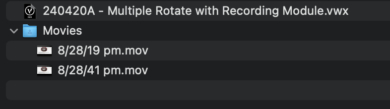
@Cody Worthmanˆif you mean the red diagonal striped box, that tells you the state of that viewport needs refreshing -
How do I turn off the candy cane stripe? It's not related to updating the site model. I unchecked show slope A. & slope B, but I am still getting the box around the object.

-
Hello Raymond! What I want to do is: I have a selection of 2D-Objects. Each Object will get a shadow-Polygone. If these Polygons overlap they should be combined into one polygone. So I apply the AddSurface() Function to each combination of objects. To ease the process I skip Objects that have already been merged. And I believe to be able to keep track of the handle of the merged objects I have to only apply the AddSurface() Function when the objects actually intersect. This is what that part of the code looks like: FOR iOBJ:= 1 TO totalOBJ DO IF NOT ( shadeOBJ[iOBJ] = NIL ) THEN FOR iOBJn:= 1 TO totalOBJ DO IF NOT ( shadeOBJ[iOBJ] = shadeOBJ[iOBJn] ) THEN BEGIN temphandle:= IntersectSurface(shadeOBJ[iOBJ],shadeOBJ[iOBJn]); IF NOT ( temphandle = NIL ) THEN BEGIN DelObject(temphandle); shadeOBJ[iOBJ]:= AddSurface(shadeOBJ[iOBJ],shadeOBJ[iOBJn]); shadeOBJ[iOBJn]:= NIL; END; END; I'm not a professional programmer and there are probably much more efficient ways to do this. I guess I could separate the Objects into chunks first.