All Activity
- Past hour
-
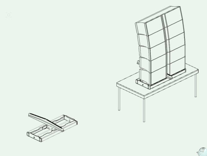
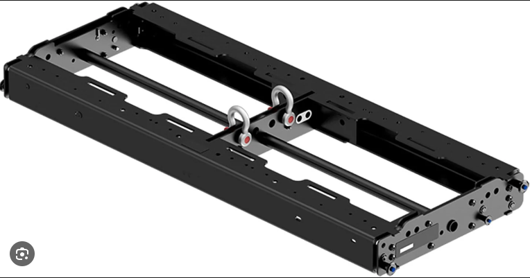
To remove the hanging bracket you will need to edit the symbol definition. first thing you need to do is import the bumper into your active file, either by inserting one on a design layer or by right clicking on it in the resource manager and selecting import. Next you need to edit the 2D and 3D components of the smybol. to this right click on the bumper symbol in youractive file resources and select either edit 2D component or 3D component. This will enable you to edit the symbol definition. Once you have completed your edits rename the bumper and save the file into either a user or workgroup library folder so its available for future projects
- Today
-

Streamdeck integration.
MD_03 replied to Matster's question in Wishlist - Feature and Content Requests
Apologies it was saying it wasn't available -
 FCFC joined the community
 -
How do I remove the hanging bracket if I am going to do a ground stack for the speakers? This is for the ground stack, with no hanging bracket.
-
Good news, @Letti R, The bug is marked as Major and will be fixed relatively quickly. I have no idea what that means in real world time, but it definitely won't sit on the back burner. Like you, I await the fix. Raymond
-
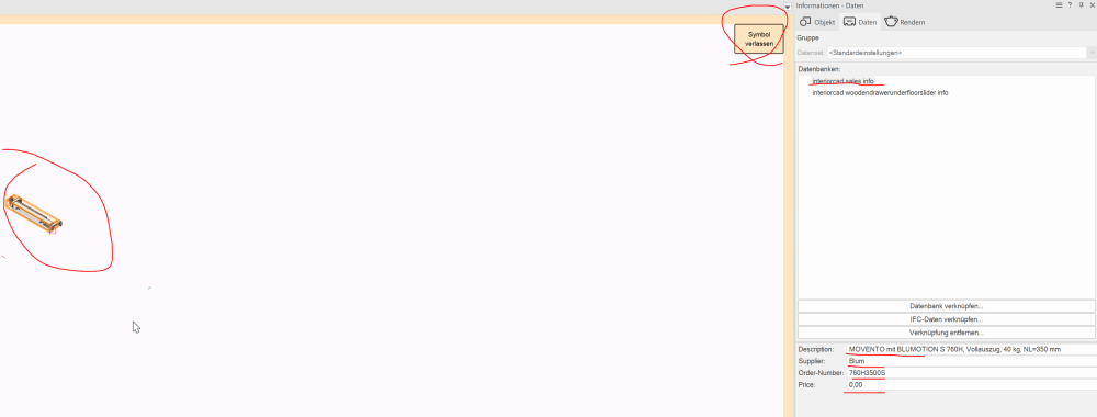
 Hello Patrick, the file has symbols. They are in the accessories manager, not on the artboard. That is my challenge. Change the database of icons in the Accessory Manager without opening it.
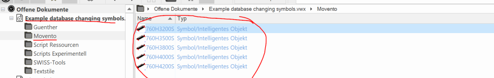
-
That's all well and good, but wait until you start writing longer scripts. Someday you'll want to look one up rather that recreate it. Either way, have fun. That's what It's all about. Raymond
-

where do I find the Vectorworks Crash-Dump-Files???
Jeremy Best replied to matteoluigi's question in Troubleshooting
Thought I'd add value to this discussion: I'm on macOS Monterey (12.7.4) and my Vectorworks crashes are recorded in the Console app. You can right-click on them to 'Reveal in Finder' which (currently) reveals that they are saved in ~/Library/Logs/DiagnosticReports/ -
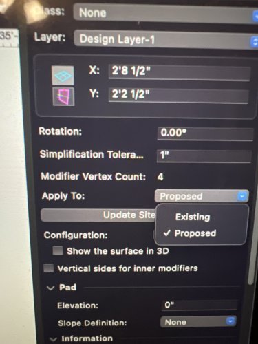
Check that your modifier has apply to proposed rather than existing. Also, check your site model settings to verify that it can communicate with the layers that your hardscape and site modifiers are on to help with predictability. You may need to use an open edge mode site modifier with snap to contours on in order to adjust the grade to get what you want inside the bounds of the grade limit. If this doesn’t work, feel free PM a copy of the file and I can take a look at it tomorrow night.
-
Hi @Pat Stanford, @DCarpenter, Here's an example using vectors, as requested, and a little more, 😉, though HScale2D() may be quicker for lines. Where this method may be more useful is when you are working with a Polygon and want to move a vertex without changing anything else. As with anything, "Actual mileage may vary." Scale a line using a vector approach: PROCEDURE xxx; { Test script to set new line length using vectors. } { 22 April 2024 - Raymond Mullin } VAR H :Handle; NewLength :Real; procedure SetLineLength(H :Handle; NewLength :Real); { Sets length of line H to new value NewLength. Point P1 is the anchor point.} Var P1, P2 :Vector; Begin GetSegPt1(H, P1.x, P1.y); GetSegPt2(H, P2.x, P2.y); P2 := P1 + UnitVec(P2-P1) * NewLength; SetSegPt2(H, P2.x, P2.y); End; { SetLineLength } BEGIN H := FSActLayer; NewLength := RealDialog('How long?', concat(hLength(H))); if not DidCancel then SetLineLength(H, NewLength); { changes line length to new value } SysBeep; { make noise when done } END; Run(xxx); If you want to scale the line in the other direction, swap the vectors P1 & P2 as shown in the following line. P1 := P2 + UnitVec(P1-P2) * NewLength; Here's an explanation of the expression: P2 := P1 + UnitVec(P2-P1) * NewLength; 1) Where P1 and P2 are both vectors, (P2-P1) is the vector that points from point P1 to point P2. Likewise, (P1-P2) is the opposite vector that points from point P2 to point P1. 2) UnitVec() is a function that scales a vector to have a length of "1". 3) A constant times a vector scales the vector, so scaling a unit vector by the new length results in a vector of the desired length. Essentially, the length is changed, but the direction remains the same. 4) Since vectors are positionless, adding a vector to a known point will return the point that is the correct distance and the correct direction away from the known point. PS - If you are wondering why I used Vector instead of Point as the variable's data type, The UnitVec() function does not accept Point type data. Essentially I am only working with 2D data, and Point and Vector are similar, but Vector data types work in all of the Vectorworks expressions, so I always use the Vector data type. In this case the z-component of the vector is always "0" and therefor does not contribute to any of the calculations. Using Vectors for 2D calculations saves having to do data conversions in the middle of a script between Points and Vectors. Feel free to try other ways as mine is not the only one. Raymond
-
 Hello, See if this movie from Julian helps: Creating a Kerbed Road on a Site Model Using a Hardscape Cheers, Peter
 -
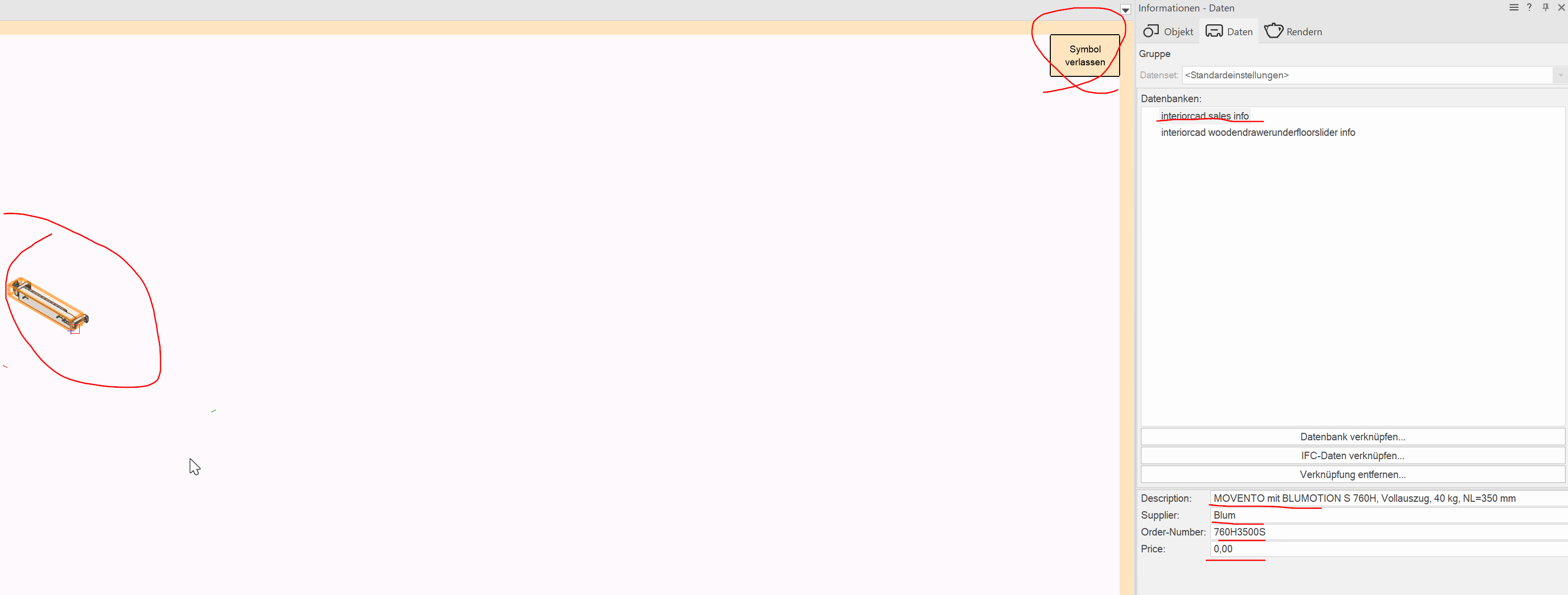
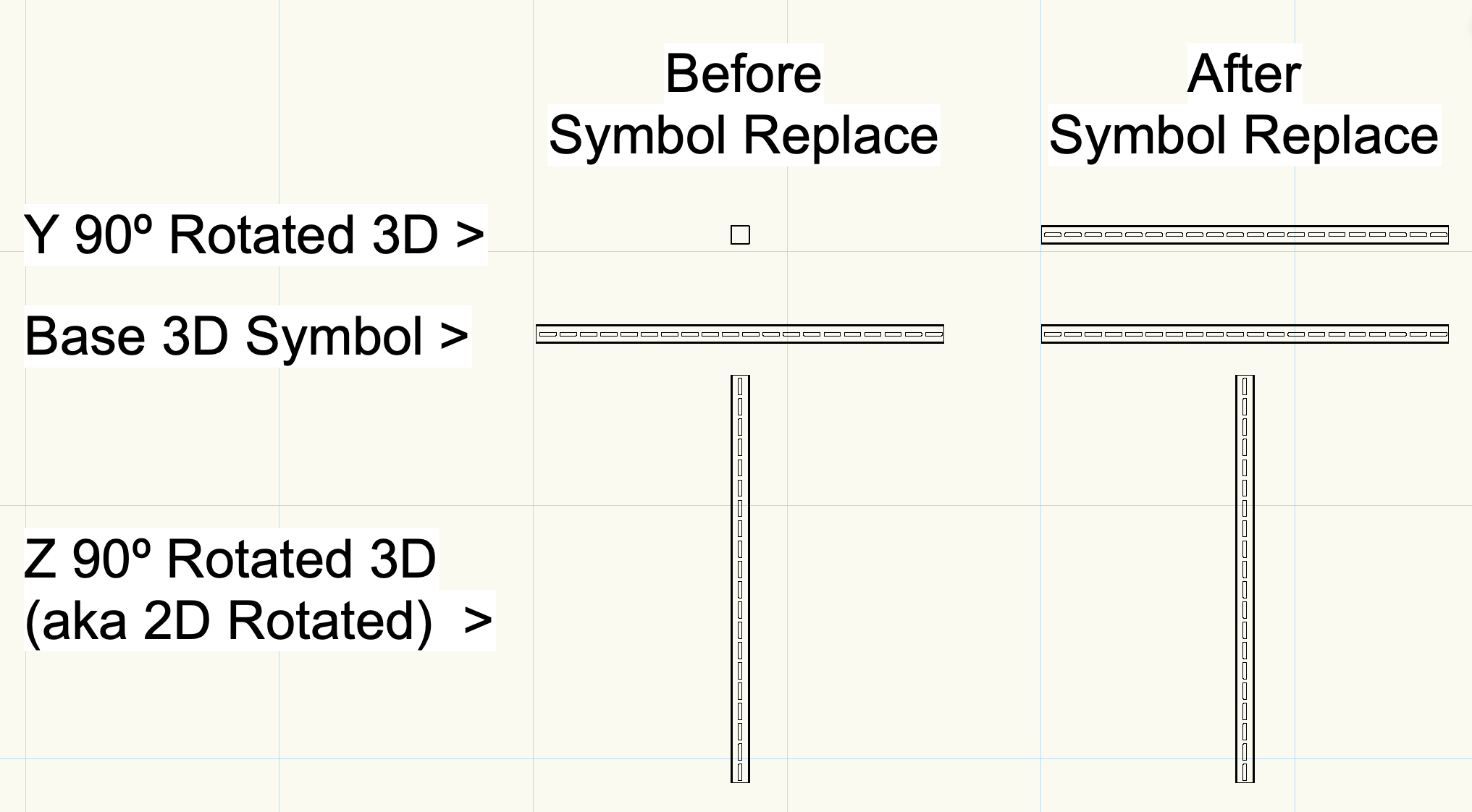
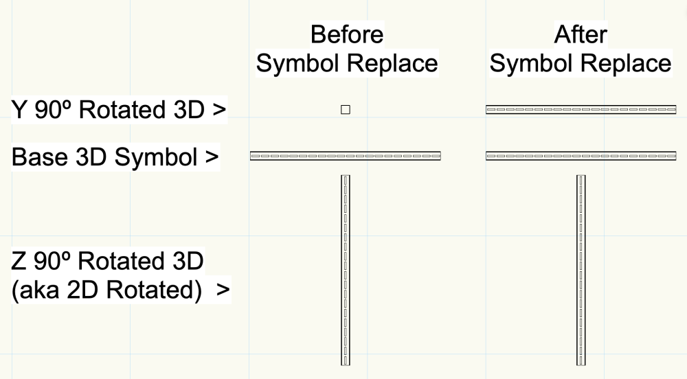
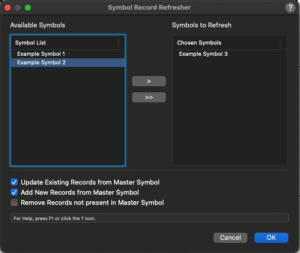
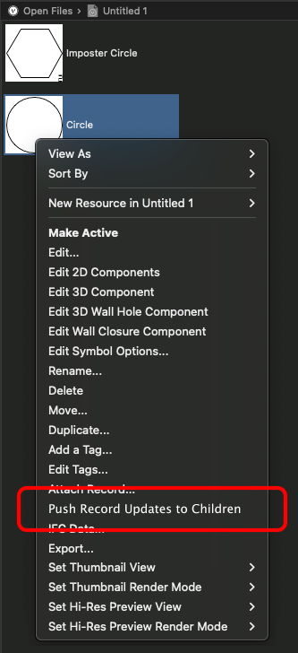
Ahoy all, Current Methodology I'm looking for other user's feedback on a methodology for Record 'Re-issuing' from the master symbol to symbols in the drawing. We know the following; Records can be attached within the symbol by selecting nothing within the edit mode of the symbol and then choosing 'Attach Record' from the POI, or via Resource Browser Right-Click Context menu (or one of about three other methods of choice). Symbols inserted after this point will automatically have the record placed upon the external container and available in the POI Data Tab. If the record field data is changed at a later stage in the Symbol Master it will not be forced to Children Symbols already present in the drawing (Agree with the methodology here 100%). The current best ways to retrospectively update Symbols already in the drawing would be; Create a worksheet summarising the desired symbols and change data manually, or; Use Modify > Convert > Replace with Symbol... and choose "Use records of substitute symbols" Although tedious these options are plausible, however not really effective on mass. The Issue The bigger issue for a client of mine currently is that the 'Replace with Symbol' method is only effective for 2D Symbols (including Hybrid) not 3D Only Symbols. When attempting Replace with Symbol in a 3D View the command is unavailable (fine). When replacing a 3D Symbol, with the same Symbol (with the intent of Record Replacement Only) the rotation is only maintained for the 3D Symbol's Z Rotation. Image showing that the Z Rotation is maintained (like a 2D Symbol) but not X/Y Rotation Although it could be argued that the Worksheet change methodology could perform this operation, this is true however taking a broader step to Record Addition, a Worksheet is unable to ADD records to a Symbol where as the 'Replace with Symbol' command can. Additionally, typically the 'Replace with Symbol' is performed in conjunction with a Group Selection (either manually, by Select Similar, or by Custom Selection) however this is sometimes not practical - especially if the desired Symbol is within another Symbol. Supporting Issues I've seen quite a few discussions on the record management from base symbol topic and think it requires an additional menu command to be considered; Proposed Solution Presuming that I'm not missing another working solution, noting that OBCD is possible but tedious (from experience) I would propose the following two options - however welcome feedback on options. Creation of a menu command which opens a modal dialog listing all Symbols in the document. An example / proposed dialog is below; A right click context menu from the Resource Browser allowing for easy single Symbol (and subsequent record) updates to instances throughout the document. However, I'm just one user's perspective from many. If you've got a different method that I've missed amongst the Data Manager or Record Commands I'd love to hear them. Then I guess I'll move this topic to the Wishlist... Cheers, J
-

Candy cane stripe around Hardscape object
Cody Worthman replied to Cody Worthman's question in Troubleshooting
I ended up deleting the offending hardscape style so I never accidentally use it again, but will keep that technique in mind if I come across the same behavior in the future. I definitely tried this method and was hopeful; but it didn't work, so I ended up rebuilding an identical hardscape style as a workaround. Will definitely keep it in mind for troubleshooting future issues. -
 pkaur joined the community
 -
 Backup your file first and make a copy to send. Then, you can delete the sheet layers and design layers that are not needed for a discussion and purge it. That should get rid of things quickly. You can post it here and others can see it or you can send it to me via a private message.
 -
 dtatarski joined the community
 -
 Chatoyer joined the community
 -
We are a textile fabricator in Australia. As a part of our fabrication process, we produce product drawings confirming dimensions for client sign off. The drawings are simple 2D drawings and we have CAD files from previous work which could be used. Please contact me if you are based in Australia and this is a service you can provide.
-
 @Jeff Prince Ooops! Yes, those are 2D polygons in 3D space. Regarding how they appear in VPs, now some VPs display them correctly; others do not. Is there a way for me to share the file with only you? I'd also like to eliminate our titleblock, or at least our stamp and signature, before I send our VW file, but I don't know how to eliminate the TB and VW won't allow me to delete the class that contains our stamp and signature. Ed
 - Yesterday
-

Vectorworks 2024 painfully slow on otherwise fast PC
rDesign replied to Raja's question in Troubleshooting
See the following post for instructions on downloading an older SP. Not sure if you are on Windows, but you'll need to find and run the Vw Updater application; other users have said that in Windows the Updater application is also in the VW App Folder, but it is in a VW Updater Sub Folder. -
Are you sure about that? Hatches are a 2D graphic that can be applied to 2D polygons or 2D polygons that have been drawn in 3D space... not typically 3D Polygons. Post the file and more detailed help can be provided.
-
I'm answering my question. I first changed settings in the object info box, then the organization window, in the wall style window and then the component edit where I was finally able to edit the component bottom. I'm realizing there are several places that have settings for the same thing but some override others.
-
 mariamabbasi joined the community
 -
does anyone know how to make a dome shaped roof?? (a year 2 architecture student) :)))
-
 UbvpwcElova joined the community
 -
Delving into this...another question: In calculating Pipe-and-Drape panel counts, the tool "sees" each upright-to-upright segment independently. So...on the "horseshoe" pipe-and-drape run, each upright-to-upright segment that is equal-to or less-than the stock drape width "gets" a panel. So, using your 4m example, "11" is correct..."Working As-Designed." IF, though, you are wanting to (essentially) ignore the uprights, the overall run length is 31.78m and the panel count would be 8. Is THIS what you're wanting? This is a very different animal. The overlap graphic display issue I mentioned is not W.A.D... 😞 I also sent you a DM..
-
I talked to Scott my rep, he is helping mr sort it out. thanks
-
I'm just getting started using VW as a BIM so I'm not sophisticated enough to put my frustrations into a cogent question. Basically, I started a file using the template which had the 2 stories(10' floor to floor with 12" slabs) plus the foundation and roof stories. I built a simple model using all the default floor settings and unstyled 9'-0" walls and slabs. I changed the slab to from the default 6" to 12" because that's how the stories are set up (9+1=10). Everything lined up. I then changed the walls to the provided 2x6 exterior wall type and the bottom of the wall moved to the bottom of slab as opposed to sitting on top of it like it was before. How do I get this moved up to the top of slab. I changed the "bottom bound" to "top of slab" and all other options but nothing changed except the location of the white square grips. I have used all the default setting so far other than changing the default slab from 6 to 12".
-
In terms of the 3D tools in the detailing toolset (i.e. I-Beam 3D), I don't really know what their relationship is to the structural member tool. I suspect the 3D detailing tools have been there for a while and the Structural Member is a more modern, all-in-one tool. Sometimes older tools/commands remain in the software for those that are used to them or have templates/processes that rely on them. As for the 2D detailing tools, it's quite common (in my experience) for engineers to model a whole structure without necessarily drawing every nut and bolt in 3D, and then place a separate 2D detail view showing a typical connection in full detail - detailing. In the world of BIM where each object has to exist in 3D to be part of the model exchange process, I think it's probably more common that steelwork designers are modelling each connection in detail, but I certainly know engineers who still do a 2D detail view on a sheet of a typical connection in the structure.
-
 The Script was made, screenplane planar objects was still a standard. it would still work with grouped screenplane objects. It seems, that the dup-container node puts screenplane planar objects on the 2D representation of the PlugIn. And grouped layerplane planar objects were putted on the 3D component of the plugIn. If we switch on top view we can see the groupes. Thanks for sharing that issue.
 -
Hello, I'm new to Vectorworks and data tags. I need to update my sheet layers so the unit text on each floor plans are designated as LH or RH, depending on which side of the hallway they're on. The floor numbers (cyan) are static values The unit numbers (blue) are sequential and are driven by the "Edit Tag Data...", as 01, 02, 03, 04, etc.... How would I create the data tag layout string values (yellow) and be able to switch between LH or RH?