Jump to content
  • 0

Issue Exporting to Aspire for CNC Milling


Alex M

Question

Hey,


I'm breaking down a desk I designed in Vectorworks so the components can be cut on my shop's CNC machine. I work on a Mac and our tool path software, Aspire, is on a PC.


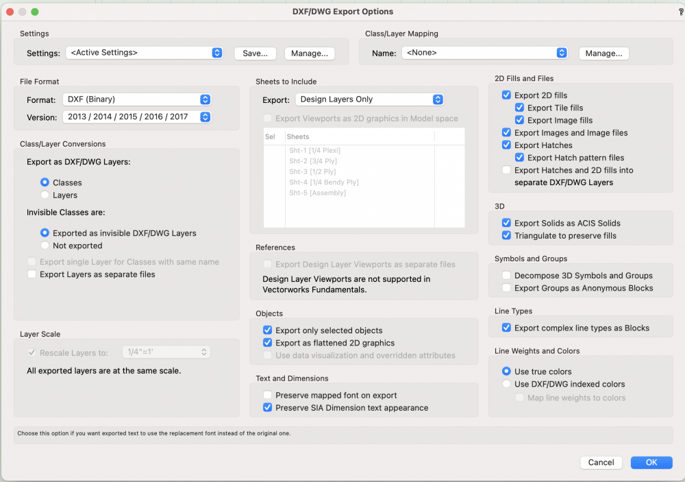
This is my workflow: design in 3D in Vectorworks > break apart the 3D the model into components to be cut on the CNC > lay the components flat in a design layer > export the layer to a DXF on a share Dropbox > open in Aspire to make the tool path.


When we try to open the file in Aspire though, we see nothing. The DXF will load in Adobe Illustrator, but with artifacts like weird lines running through the shapes that need to be deleted. The components also shrink in size when I do this.


Any thoughts for making this process easier?


Alex

Screen Shot 2021-10-27 at 5.06.53 PM.png

Edited by Alex M
Link to comment

9 answers to this question

Recommended Posts

  • 0

Not sure this is solution, but

Try exporting the dxf/dwg in ASCII format rather than the Binary. Aspire might not read Binary even though AI does. Here is a bit about the differences. https://cadpanacea.com/wp/?p=60


The Export dialog shows “Export only selected objects”.
If nothing selected, export will be blank. 

Those options to include images, fills and hatches might mess up a process based on perimeters and holes linework. Suggest disable them unless needed. 
 

Post back with solution when you get it working. 

-B

Link to comment
  • 0

Everything seems to be working now! I changed a few things about my workflow, let me know if any of this seems extraneous.


Here's my workflow:

Convert to Polygons

Render to Final Quality Renderworks

Export with the settings in the image below.


I added the Final Quality Renderworks step because one of my earlier tests turned a curve into a chunky hexagon when it came time to cut this shape out of 3/4 plywood. I'm not sure what happened there, but I thought maybe it was because I exported from a layer that was rendered in Wireframe mode?

Screen Shot 2021-11-01 at 5.39.36 PM.png

Screen Shot 2021-11-01 at 5.43.53 PM.png

Link to comment
  • 0

I think @Pat Stanford has it right. Conversion resolution rather than Render state is likely culprit for faceted curves. I also think wire frame is your friend. It is more WYSIWYG. The rendered version definitely affects screen display and print, but probably does not affect the exported vectors (can anyone verify that?). Final Quality RW does not render curves at highest possible setting. Look into Custom Render to optimize display of curved geometry. 

Anyway glad you made it work! Since you have in-house cutting you can, and should, look at a proof of the Aspire paths on screen to verify conformity prior to starting a cut job. 
 

My experience:

For CNC, the cutting paths are only export requirement. I suggest disable export of Fills,hatches, etc. they may port out as separate files, but might get included with the vector paths. Hopefully Aspire can reliably filter or ignore, but if not they could introduce extraneous paths causing repeat passes or incorrect kerffing or even unintended cuts or pierces.


If inclined, post a photo of some CNC parts or your assembled desk. 

-B

Edited by Benson Shaw
Thumbs, auto correct. What could go wrong?
Link to comment
  • 0

It's not that difficult. A few basic rules when exporting to 2D CNC though: 

Keep it as simple as possible. Use text code instead of binary. Do not use things like symbols, fills, etc. Avoid Splines, Berzier curves, NURBS curves, etc, convert to plain polygons at reasonable resolutions. If curves are used, be sure to use arc based segments. Object types should be restricted to lines, circles, arcs. Decompose polygons having for example holes etc inside using Clip Surface. For milling, where the tool as a diameter, be sure to place objects inside objects in a different class or layer, as they should cut from the inside instead of the outside of the contours. Cuts and Incuts are not the same thing there. Check if the receiving program uses some sort of industry standard layering system, and if so, follow it. 

Link to comment
  • 0
13 hours ago, Benson Shaw said:

Conversion resolution rather than Render state is likely culprit for faceted curves.

But both Shaded (previously OpenGL) and Renderworks and Red Shift all have options for Curved Geometry in their settings. It is likely that the styles you uses just happened to have the Curved Geometry settings to something other than Low.

Link to comment
  • 0
On 11/2/2021 at 4:47 AM, Claes Lundstrom said:

It's not that difficult. A few basic rules when exporting to 2D CNC though: 

Keep it as simple as possible. Use text code instead of binary. Do not use things like symbols, fills, etc. Avoid Splines, Berzier curves, NURBS curves, etc, convert to plain polygons at reasonable resolutions.

If curves are used, be sure to use arc based segments. Object types should be restricted to lines, circles, arcs. Decompose polygons having for example holes etc inside using Clip Surface. For milling, where the tool as a diameter, be sure to place objects inside objects in a different class or layer, as they should cut from the inside instead of the outside of the contours. Cuts and Incuts are not the same thing there. Check if the receiving program uses some sort of industry standard layering system, and if so, follow it. 


Thanks for all the responses. My 2D conversion resolution was actually set at High, so I'm not sure what happened there.


What do you mean by this? "If curves are used, be sure to use arc based segments."


Or this? "Decompose polygons having for example holes etc inside using Clip Surface."


I guess by the latter you mean if I was making a top for my desk that looked like Swiss cheese using "Clip Surface" to cut out my Swiss Cheese holes, I should Modify>Decompose that resultant shape before export?


Link to comment
  • 0

@Alex M Some things from my experience with prepping for CNC and observing vwx.

  • When selected, vwx curves display faceted highlights if 2d Conversion Res is set to Low. Zoom in to see it. Any render state.
  • In TopPlan, when not selected, 2d curves display without facets, even if 2d Conversion Res is set to Low.
  • In Top (any render state), the same 2d curves will display the facets, both when selected, and when NOT selected.
  • DWG export of rendered state round trips back to vwx such that TopPlan displays no facets (but highlights faceted), and Top displays the facets. Unfortunately, I have no direct dwg importer, so cannot predict faceting in dwg native software.
  • Higher Conversion Resolution states reduce the faceting in TopPlan.

Conclusions - Use TopPlan and Wire Frame render for the export. Raise the Conversion Resolution to highest state.


Re arc based segments (my take) - This used to be super important, and is probably best practice overall.  Don't use Bezier or Spline curves.  Older CAM software may not interpret these properly.  If these curves are present, test in the CAM before any cuts, and if needed, redraw with arcs and lines, or apply the Poly Smoothing>Arc command (rebuild the corner points with the Reshape tool).  Some newer CAM software can properly interpret Bez and Splines.  Dunno about Aspire or versions thereof.


Re Decompose (my take) - Example, a square with a round hole in it.  If the two are selected and the Clip Surface command is applied to create a single poly with a hole, the circle is no longer a simple shape.  Edit Poly to see this - the circle is now a series of arc polys. The CAM might interpret this incorrectly and kerf the hole on outside instead of inside.  Or, may cause more cutting time, or distortion as machine slows to meet the corners.  Again, may be more important for older CAM and less problematic for newer versions.

        Also, any future edits to the hole size require delete the internal poly and replace with new circle (which converts to arc poly when exit the edit window).

        I usually use 2 or more files to create a cutting export -

  • 2d symbols, holes and perimeters are separate objects rather than clipped clipped surfaces. Design/edit in this file.
  • Send these symbols to a separate "cutting" file for dwg export. In this fileConvert to Group and Ungroup prior to dwg export. If edits in the design file, delete all and copy the new versions into this file. Convert to Group, Ungroup, export to dwg. 
  • The 3d model needs the clipped surfaces for extrudes, so that is a separate layer in the design file with separate 3d symbols.  This 3d stuff is never sent into the cutting file.


@Claes Lundstrom may have more detail, but the advice is sound.  Always proof in the CAM prior to cut. Newer CAM and newer dwg revs may allow more flexibility.


-B


image.thumb.png.7aee57d31ab5da3ea8144ed3a68de8c1.png

Edited by Benson Shaw
review, rewrite, review, rewrite, . . .
Link to comment
  • 0
13 hours ago, Alex M said:


Thanks for all the responses. My 2D conversion resolution was actually set at High, so I'm not sure what happened there.


What do you mean by this? "If curves are used, be sure to use arc based segments."


Or this? "Decompose polygons having for example holes etc inside using Clip Surface."


I guess by the latter you mean if I was making a top for my desk that looked like Swiss cheese using "Clip Surface" to cut out my Swiss Cheese holes, I should Modify>Decompose that resultant shape before export?


The three point arc mode in the Reshape tool creates arcs like in the picture, where I exaggerated  the shape to illustrate it. In reality you need to fine tune it more. This typically works best of the arcs as they are seen as just arcs by many cutter being next to one another 


The Blue circle is just one object being on top of another, which works better that the second option, where there is a physical hole in the rectangle. You can however achieve this by exploding the model before exporting to the cutter. The fist option is what I typically use within VW as its much more logical.


Skärmavbild 2021-11-04 kl. 11.43.19.png

Link to comment

Join the conversation

You can post now and register later. If you have an account, sign in now to post with your account.
Note: Your post will require moderator approval before it will be visible.

Guest
Answer this question...

×   Pasted as rich text.   Restore formatting

  Only 75 emoji are allowed.

×   Your link has been automatically embedded.   Display as a link instead

×   Your previous content has been restored.   Clear editor

×   You cannot paste images directly. Upload or insert images from URL.

×
×
  • Create New...