Jump to content
  • 19

Section lines that can bend, not just step


Christiaan

Question

Recommended Posts

  • 0
16 hours ago, Jonathan Pickup said:

I used to create two sections, but it was a messy way to do it. 


Yeah, I was actually going to mention that. That's how we currently work around it but it's time-consuming and messy, and it amplifies the number of errors you can make. Especially when you have a faceted building like the one I'm modelling now, needing six separate sections to take a long section through it.

Edited by Christiaan
Link to comment
  • 0
3 hours ago, tdiamond said:

@Amorphous - Juliansent this question through via tech support…


Echoing @Jonathan Pickup, just use two section VPs in partial section mode (edit via the section instance, that is, the Section-Elevation Line). Where they join, add an annotation indicating the section plane pivot axis.
 

Screenshot 2023-04-17 at 10.24.56 am.png


We all do some form of this (I just crop full sections), but it is time-consuming and messy, and it amplifies the number of potential errors and problems.


Imagine you have a section with six bends (as I currently do). And imagine trying to coordinate the floor plan section line tidily with the section. Now imagine wanting to adjust that section.

  • Like 1
Link to comment
  • 0
  • Vectorworks, Inc Employee


Know the feeling. A recent project from my past life had ~40 elevations. Its general arrangement looked more like a molecule layout from chemistry class.


And yes, what you propose would be welcome.

  • Like 1
Link to comment
  • 0
  • Vectorworks, Inc Employee

I agree this would be useful but it would be a little more involved than having a section line stitch together multiple sections defined by its segments.  Doing so would result in gaps and overlaps in the geometry beyond the cut plane (for elevations).


image.png


We would need to provide a way for users to define the extents of each segment.  something like this:


image.png

  • Like 4
Link to comment
  • 0
11 hours ago, Matt Panzer said:

I agree this would be useful but it would be a little more involved than having a section line stitch together multiple sections defined by its segments.  Doing so would result in gaps and overlaps in the geometry beyond the cut plane (for elevations).


image.png


We would need to provide a way for users to define the extents of each segment.  something like this:


image.png

Yes, Maybe, Someone is bound to ask. So I guess best if first version doesn't paint the code design into a corner that can't be gotten out of. 


However the top example is what I'd expect to be cover by what is considered standard drawing convention around here. We'd just insert a little flag marker to say if internal verse and external corner. so the reader would have an idea. If the first version worked like that I'd be happy and it would streamline somethings indeed I'd suggest the most common uses cases to see if version 2 is indeed required. 


The other thing that would be great is if section lines could have an anchor point that tied them to the annotation space content. Allowing us to then the extend in or out from that point without then realigning the annotations. Useful in these cases as the 2 partial sections could share an anchor at the view fold.

Link to comment
  • 0

I agree with Matt. The first one is actually what I would expect from a section line. In a section drawing the most important content is at the cut line rather than what's in the background, if you're showing it at all.


However I can imagine the capabilities in the second example being extremely useful for drawing clarity, especially when the background content is important (such as using it to create elevations), but also when doing a section and aligning to the background in this way doesn't compromise the section information.

  • Like 1
Link to comment
  • 0
  • Vectorworks, Inc Employee
9 hours ago, Matt Overton said:

Yes, Maybe, Someone is bound to ask. So I guess best if first version doesn't paint the code design into a corner that can't be gotten out of. 


However the top example is what I'd expect to be cover by what is considered standard drawing convention around here. We'd just insert a little flag marker to say if internal verse and external corner. so the reader would have an idea. If the first version worked like that I'd be happy and it would streamline somethings indeed I'd suggest the most common uses cases to see if version 2 is indeed required. 


The other thing that would be great is if section lines could have an anchor point that tied them to the annotation space content. Allowing us to then the extend in or out from that point without then realigning the annotations. Useful in these cases as the 2 partial sections could share an anchor at the view fold.


8 hours ago, Christiaan said:

I agree with Matt. The first one is actually what I would expect from a section line. In a section drawing the most important content is at the cut line rather than what's in the background, if you're showing it at all.


However I can imagine the capabilities in the second example being extremely useful for drawing clarity, especially when the background content is important (such as using it to create elevations), but also when doing a section and aligning to the background in this way doesn't compromise the section information.


I agree that both are important depending on the drawing.  So the real question is: Would you ever use a bent section line in a floor plan drawing that refers to elevation drawings or would you use interior elevation markers for that?

Link to comment
  • 0
On 1/5/2021 at 5:20 AM, Christiaan said:

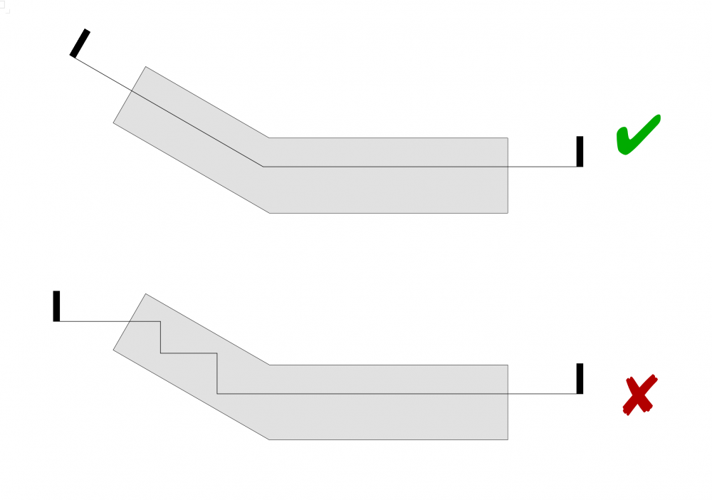
We need to be able to create Section Viewports by bending section lines rather than stepping them. Stepped section lines make for some very messy sections on some building shapes.


This whole thread is interesting, but it begs to question...

Is this an actual Architectural sectioning technique?

I thought the "rules" for sections and elevations was a primary view is chosen which the picture plane is parallel to and then all other features not on the plan are projected/foreshortened.


It seems that a different tool would be needed than the conventional section line tool in order to do this properly.


I would like to see something like a clip cube, where you could draw an angled polygon to define what you want to keep and then have the stuff outside the polygon removed.  Now that would be useful.  You could then orientate an elevation to this clipped form and have everything projected, either orthographically or in perspective.


Edited by jeff prince
Link to comment
  • 0

I think that is a quite difficult Feature Wish.


I wouldn't even know where/which depth I should place my cut line.

Or if there are any official standards on how to do or what to show.


After watching @Matt Panzer examples I rather think there can't be

a real solution and offering all options ending being clumsy and expensive

to develop.

And for a quite rare use case which you could workaround with a set of

Sections, finally aligning the SLVPs.


And my current estimated best (and honest way ?) to do so would be even

to do not combine the separate Sections, but show all with some side extension

separately, where the extensions clearly show that there is strange geometrical

stuff happening at the sides .....

Maybe showing everything distorted in gray.

  • Like 1
Link to comment
  • 0
  • Vectorworks, Inc Employee
15 minutes ago, zoomer said:

I think that is a quite difficult Feature Wish.


I wouldn't even know where/which depth I should place my cut line.

Or if there are any official standards on how to do or what to show.


After watching @Matt Panzer examples I rather think there can't be

a real solution and offering all options ending being clumsy and expensive

to develop.

And for a quite rare use case which you could workaround with a set of

Sections, finally aligning the SLVPs.


And my current estimated best (and honest way ?) to do so would be even

to do not combine the separate Sections, but show all with some side extension

separately, where the extensions clearly show that there is strange geometrical

stuff happening at the sides .....

Maybe showing everything distorted in gray.


The more I think about this, the more I tend to agree that there's no good way to deal with the elevation behind the section cut.  I think the section cut should accurately follow the shape of the section line that you see on the plan.  If anything, maybe the section viewport would show an accurate cut and the user could crop the horizontal extents of each bend segment.  But that still has issues when the angle between bends is acute causing the extents beyond to overlap each other.  Probably the best way to handle this would be to have Vectorworks create separate section viewports that would be associated to each bend segment of the section line.  These viewports could be initially created side by side up against each other and the user could then adjust them as needed.

Things to think about... 🙂 

  • Like 2
Link to comment
  • 0

For my purposes, I would accept the fact that a bent Section cut would not show any extents beyond.  I could then "fake" the extents via annotations, interior elevations, etc.  This wouldn't work well for section perspectives, but would match what we used to do in hand-drawn construction drawing sections.

Link to comment
  • 0
11 hours ago, Matt Panzer said:


I agree that both are important depending on the drawing.  So the real question is: Would you ever use a bent section line in a floor plan drawing that refers to elevation drawings or would you use interior elevation markers for that?

I'd use elevation markers as we'd generally also have annotations between each IE. 

Where a bent sections is a tool for showing the direct sectional relationship at that fold line. 

Link to comment
  • 0
8 hours ago, Matt Panzer said:


The more I think about this, the more I tend to agree that there's no good way to deal with the elevation behind the section cut.  I think the section cut should accurately follow the shape of the section line that you see on the plan.  If anything, maybe the section viewport would show an accurate cut and the user could crop the horizontal extents of each bend segment.  But that still has issues when the angle between bends is acute causing the extents beyond to overlap each other.  Probably the best way to handle this would be to have Vectorworks create separate section viewports that would be associated to each bend segment of the section line.  These viewports could be initially created side by side up against each other and the user could then adjust them as needed.

Things to think about... 🙂 

Not suggesting it is easy but there are any number of objects that could benefit from a Along a path mode.

A generalised plug-in smart container for this could be useful. 

  • Like 1
Link to comment
  • 0
2 hours ago, Matt Panzer said:

Another example I often hear of is a bent section line placed along a winding hardscape path in a landscape drawing

Yeah, that's a lot like the needs of road engineering... would be nice to have topographical elevation depicted at centerline of hardscape path & profile cross sections.  Currently, we have to draw this manually, if they are required.


@Christiaan That's a really great building example since it is both curved and steps down in elevation, thanks for sharing.  Nice work.

  • Like 2
Link to comment

Join the conversation

You can post now and register later. If you have an account, sign in now to post with your account.
Note: Your post will require moderator approval before it will be visible.

Guest
Answer this question...

×   Pasted as rich text.   Restore formatting

  Only 75 emoji are allowed.

×   Your link has been automatically embedded.   Display as a link instead

×   Your previous content has been restored.   Clear editor

×   You cannot paste images directly. Upload or insert images from URL.

×
×
  • Create New...