Hello, As I muddle my way through learning new (to me) features of VW on my own, I find myself stuck. In the meantime, seeking advice from the helpful community here. I have created a site model from survey data that is accurate enough for my needs. I've added pads where a new structure will go, one a bit lower for a garage, another a little higher for crawl space, and a third that is an existing slab in a garage that will be torn down. Will keep that slab. Elevations of the pad are roughly 221', 222' and 223'. The site ranges from about 221' to about 230' at it's highest point. (An urban single family lot). I have the site model set to a lowest elevation of about 218' so I have a little bit of thickness to it. When I add the site modifiers, it seems those default to a zero reference point. (I don't even know if I'm describing this correctly) Some screen shots attached. I guess if this is how they have to be, so be it, but I'd like to bring the bottom of the site modifiers up to align with the bottom of the site model. When I bring up the "Geometry Lowest X" it moves the whole model of course. So I keep that at zero. Workarounds, other elegant drafting solutions, tips, tricks and magic appreciated. The goal is really to automate the elevations and sections relative to the site so I don't have to draw in grade lines around the building, cross referencing the survey as I go along, and then having to make changes to that if the building height gets changed for whatever reason. I haven't figured out how to use this well with an elevation except to create a section viewport from a clip cube, with the clip just beyond the building, and apply soil hatch to the cut portions. Alas, I can't seem to change the cut plane- so where I've cut through part of a roof overhang with a clip cube, the fascia shows as soil. I suppose in a section view, the drawing solution would be to create the section as two viewports. One with the building, one with the site model, and create a crop object on the site viewport that cuts out the building area foundation walls and footings. My goal is good looking drawings with as much automation as possible. Also, this file crashes daily. Is that an issue others find when using site models?
You can post now and register later.
If you have an account, sign in now to post with your account.
Note: Your post will require moderator approval before it will be visible.


Question
jtempleton
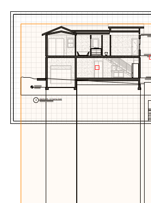
Hello, As I muddle my way through learning new (to me) features of VW on my own, I find myself stuck. In the meantime, seeking advice from the helpful community here. I have created a site model from survey data that is accurate enough for my needs. I've added pads where a new structure will go, one a bit lower for a garage, another a little higher for crawl space, and a third that is an existing slab in a garage that will be torn down. Will keep that slab. Elevations of the pad are roughly 221', 222' and 223'. The site ranges from about 221' to about 230' at it's highest point. (An urban single family lot). I have the site model set to a lowest elevation of about 218' so I have a little bit of thickness to it. When I add the site modifiers, it seems those default to a zero reference point. (I don't even know if I'm describing this correctly) Some screen shots attached. I guess if this is how they have to be, so be it, but I'd like to bring the bottom of the site modifiers up to align with the bottom of the site model. When I bring up the "Geometry Lowest X" it moves the whole model of course. So I keep that at zero. Workarounds, other elegant drafting solutions, tips, tricks and magic appreciated. The goal is really to automate the elevations and sections relative to the site so I don't have to draw in grade lines around the building, cross referencing the survey as I go along, and then having to make changes to that if the building height gets changed for whatever reason. I haven't figured out how to use this well with an elevation except to create a section viewport from a clip cube, with the clip just beyond the building, and apply soil hatch to the cut portions. Alas, I can't seem to change the cut plane- so where I've cut through part of a roof overhang with a clip cube, the fascia shows as soil. I suppose in a section view, the drawing solution would be to create the section as two viewports. One with the building, one with the site model, and create a crop object on the site viewport that cuts out the building area foundation walls and footings. My goal is good looking drawings with as much automation as possible. Also, this file crashes daily. Is that an issue others find when using site models?
Edited by jtempletonLink to comment
2 answers to this question
Recommended Posts
Join the conversation
You can post now and register later. If you have an account, sign in now to post with your account.
Note: Your post will require moderator approval before it will be visible.