Jump to content
  • 2

Point size control for Point Clouds


JeremyLondonRMLA

Question

Does anyone know if there's a way in Vectorworks to adjust the point display size on imported point clouds, such as LAS files.


At present I find that point clouds display well at a distance, see attached image 1, but when I zoom in to inspect closely and snap a 3D locus/stake object to a point to confirm its coordinates, the point cloud becomes very difficult to interpret due to the sparsity of points against the surrounding background, see attached image 2.


I've tried adjusting the pen thickness of the point cloud object in the attributes pallette / class settings, and searched in Vectorworks Preferences for any relevant settings, but had no luck so far.


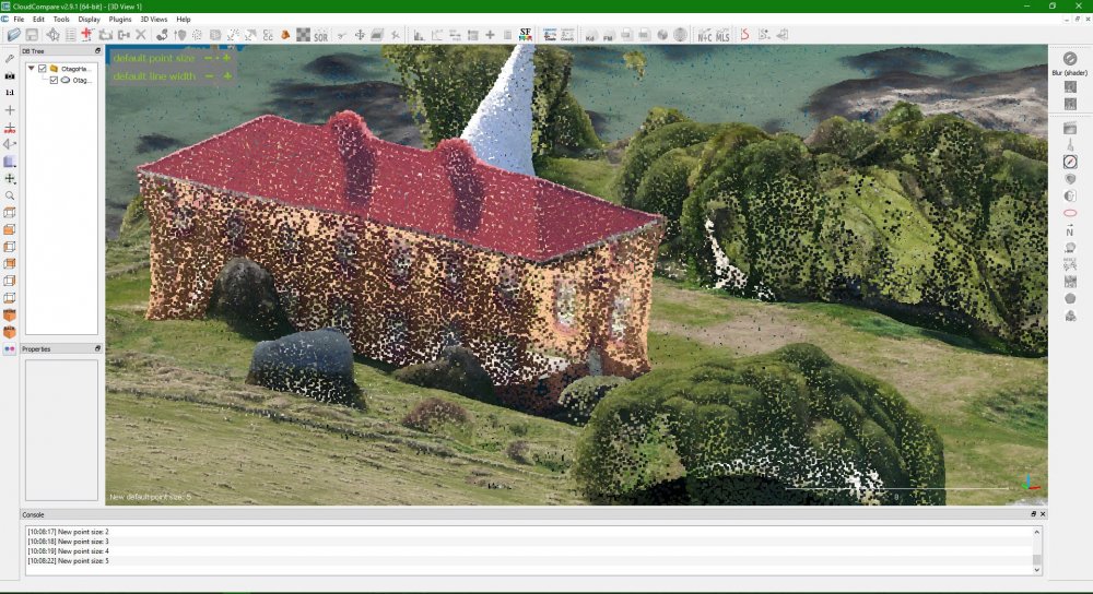
I've discovered a very useful open source program called CloudCompare for the inspection of point clouds. This program allows the user to adjust point display size which really helps with interpretation at close range, see attached images 3-5. Note the 'default point size' adjustment buttons in the top left. 


If similar control over point size display could be added to Vectorworks I believe it would greatly improve the point cloud workflow.


Lidar_Vectorworks.jpg

Lidar_Vectorworks_Zoom.jpg

Lidar_Cloud Compare.jpg

Lidar_Cloud Compare_Zoom.jpg

Lidar_Cloud Compare_Zoom_Increase Point Size.jpg

Edited by JeremyLondonRMLA
  • Like 1
Link to comment

Recommended Posts

  • 0

I have messed around with the "shell solid" command to see if I can put an even coating of hempcrete onto the wonky wall. I can sort of.


1139785283_Screenshot2021-08-29at10_17_11.jpg.d443a51149c925d5cd463b92c2caaa1e.jpg


I don't actually think this is a feasible way of adding layers to a wall as it would not really be subsequently editable.


Also, I don't entirely understand the "shell solid" command; it seems to do the opposite to what I want - it seems you have to select all the faces you don't want it to create a shell from?

Link to comment
  • 0
24 minutes ago, line-weight said:

I don't actually think this is a feasible way of adding layers to a wall as it would not really be subsequently editable.


I agree tempting as it is to build the model authentically like this it would be so much work + I'd end up with something completely 'dumb'. 

1386798967_Screenshot2021-08-29at10_35_59.thumb.png.399efc82c19682c25ac81a5957e4f87f.png2107502823_Screenshot2021-08-29at10_35_23.png.7cf039ab82fed853d326409ed80ab400.png


I'd much rather forfeit the slanting walls for a model where I can add an inch of hempcrete everywhere with a couple of clicks + learn immediately how this impacts on thermal performance + cost. At the end of the day I need to remember it's the functionality of the model that's more important than the aesthetics.


Having said that I may end up doing it in a few select instances in order to generate particular drawings. But then like you say you run the risk of creating two models simultaneously + doing the work twice... I'm just going to play it by ear + see what happens.


26 minutes ago, line-weight said:

Also, I don't entirely understand the "shell solid" command; it seems to do the opposite to what I want - it seems you have to select all the faces you don't want it to create a shell from?


Not sure I've experienced this

Link to comment
  • 0
24 minutes ago, Tom W. said:


I'd much rather forfeit the slanting walls for a model where I can add an inch of hempcrete everywhere with a couple of clicks + learn immediately how this impacts on thermal performance


I'm going increasingly off topic but do you feel that you are able to extract this kind of information meaningfully from a VW model?


Essentially do you mean you can extract a total external wall area?


(If I'm doing U-value calculations, I'm not doing them in VW but in a separate calculator)

Link to comment
  • 0

Reporting on component quantities (surface area + volume): definitely. If you are strict about your component names you can use the ‘CompVolumeByName’ + ‘CompAreaByName’ functions then easily convert the results into no. sheets plasterboard, linear metres of 4x2, no. bags multifinish, etc. This is really important for me because most of the time I'm running refurb projects + ordering the materials.


Thermal performance I'll have to get back to you because the wonky-walled-barn project is the first one I've wanted/needed to calculate it! I try to remember to enter the k-value for my wall/slab/roof components when creating styles, then I get the r-value for the wall/slab/roof as a whole.


1691663542_Screenshot2021-08-29at11_36_49.png.b2d26438f330375e77ef00804aed1055.png1768855733_Screenshot2021-08-29at11_37_11.png.e59a0d4028f9902be5e49987efcd4df3.png


But not taken it any further than that yet. I guess I'm thinking that I can use Energos to give me a ball park idea for how the building is performing + get a sense of how different types/quantities of insulation are going to affect it overall before getting proper SAP calcs done. Then I'll be able to see how VW assessment compares.


Any advice you have in this area would be welcome. How are you making your calculations?


There was recent webinar on Energos but only watched half of it... Need to look into it properly...

Link to comment
  • 0
1 hour ago, line-weight said:

Also, I don't entirely understand the "shell solid" command; it seems to do the opposite to what I want - it seems you have to select all the faces you don't want it to create a shell from?


Exactly.

By selecting Faces you will create openings.

Link to comment
  • 0
5 minutes ago, zoomer said:


Exactly.

By selecting Faces you will create openings.

On my walls I used Extract tool to create NURBS surfaces from the face of the wall, then activated Shell Solid tool, specified the thickness + ‘outside’, selected all the NURBS + clicked on the green tick. the face of the wall extrudes outwards into the room as a single Shell object

Link to comment
  • 0
2 hours ago, Tom W. said:


Any advice you have in this area would be welcome. How are you making your calculations?


Briefly: I mostly dot about between the online calculators that insulation manufacturers provide (eg celotex, kingspan). But there are also other online calculators (and applications). I've not looked into whether Energos does reliable U-value calculations - if it does then maybe I should look into that more. For example, can it give you calculations where an element is bridged at regular intervals (eg insulation sitting between rafters). And can it do condensation risk. And ventilated cavities.


I wonder if this deserves a thread of its own. I may come back to this later...

Edited by line-weight
Link to comment
  • 0

I imagine that where you have a timber framed wall with insulation between the studs you'd need to look at the two thermal conductivities + work out the overall lambda for that component yourself. But I have different components depending on the stud centres anyway - because I report on timber quantities based on the specific component - so this would be fine for me. It would be baked into the wall style.


This was the recent webinar on Energos:


https://university.vectorworks.net/mod/scorm/player.php?scoid=702&cm=685&currentorg=articulate_rise


Be definitely good to learn more about it from people who use it. I haven't seen a massive amount of material on it out there

Link to comment
  • 0

I've not really tried Energos because I have a feeling it's one of those VW tools that I'd invest a load of time into finding out that it doesn't actually work well enough to be useful. The documentation is scarce and there seems to be no indication it's being actively developed. There are a few threads around... you can read through them and decide whether you're braver than me!


  • Like 1
Link to comment
  • 0

Ha ha not brave but probably a glutton for punishment.


Thanks for the link.


I think if it performs as @Luka Stefanovic says then that will be enough for me:


"My general view is that Energos is a fantastic tool for Architects to understand the energy performance of their design and to do so throughout the design process. I feel sometimes users expect it to be something that it’s not - energy modelling software. Vectorworks is, as you know, a Design Software (in this case we're talking about Architectural Design) and Energos has been developed as a supplement to an Architects' workflow, not as a replacement for the likes of IES. It's based on mathematical calculations using PassivHaus methods - this is what enables it to update the results and recalculate in a matter of seconds instead of much longer times that would have been required if it were modelling the solar path and geometry to calculate shading for example. Instead, it relies on Designers' manual input to determine shading percentages for each opening, which requires either a manual detailed calculation in order to input an accurate percentage value or leads to some minor inaccuracy.

To summarise, I think if accepted for what it is, a very useful and in-depth energy performance evaluation tool to accompany your architectural design process from the very beginning, then it has a real value to Architects and gives them power to make informed design decisions at every step in that process do they can create truly sustainable and energy efficient architecture."


I will still need proper SAPS calcs for building control whatever happens, I would just like a bit of a heads up before I get to that stage

Link to comment
  • 0
On 8/29/2021 at 10:48 AM, Tom W. said:


I agree tempting as it is to build the model authentically like this it would be so much work + I'd end up with something completely 'dumb'. 

1386798967_Screenshot2021-08-29at10_35_59.thumb.png.399efc82c19682c25ac81a5957e4f87f.png2107502823_Screenshot2021-08-29at10_35_23.png.7cf039ab82fed853d326409ed80ab400.png


I'd much rather forfeit the slanting walls for a model where I can add an inch of hempcrete everywhere with a couple of clicks + learn immediately how this impacts on thermal performance + cost. At the end of the day I need to remember it's the functionality of the model that's more important than the aesthetics.


Having said that I may end up doing it in a few select instances in order to generate particular drawings. But then like you say you run the risk of creating two models simultaneously + doing the work twice... I'm just going to play it by ear + see what happens.


Not sure I've experienced this


I've been looking into VW Materials for the first time this last week or so + realised that what I said earlier about 3D solids being completely dumb + not being able to report on them without attaching Records was (since VW introduced Materials) completely wrong. If I were to model my building completely from 3D Solids + gave those objects Materials there is enormous potential for reporting quantities, R values + all sorts of other things about those objects. And using Data Tags on them.


There seemed to be quite a lot of negative press about Materials when they were introduced in VW2021 + that coupled with the fact my brain simply couldn't handle taking on anything new having spent a year getting to know VW2020 meant I avoided looking at them until now. But I have to say so far I think they're great.

  • Like 2
Link to comment

Join the conversation

You can post now and register later. If you have an account, sign in now to post with your account.
Note: Your post will require moderator approval before it will be visible.

Guest
Answer this question...

×   Pasted as rich text.   Restore formatting

  Only 75 emoji are allowed.

×   Your link has been automatically embedded.   Display as a link instead

×   Your previous content has been restored.   Clear editor

×   You cannot paste images directly. Upload or insert images from URL.

×
×
  • Create New...