Search the Community
Showing results for tags 'walls'.
-
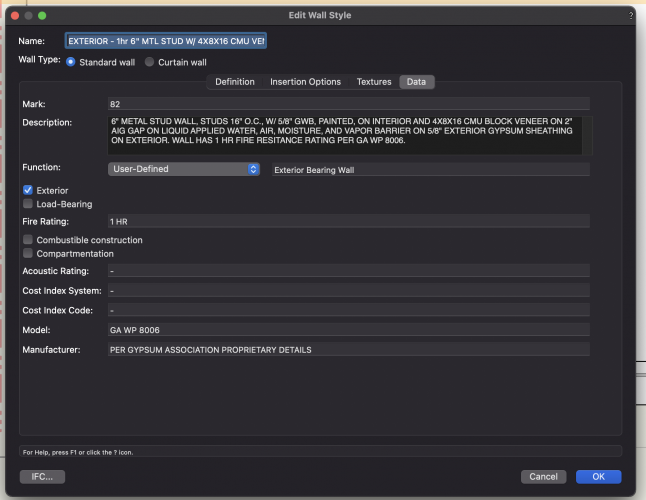
 Hi all, I’m hoping to call upon your collective expertise, I’ve a model of a small house extension, and I’d like to experiment with adding data to building elements like walls, floor and roofs etc. id really like to learn how I can tag a wall type to hold its data, like 60 or 30 minutes fire resistance. I’d also like to record its acoustic properties say 46 or 42dB for example, and a simple way of recording the uvalue of the wall type for some external walls as I build up my specifications. my idea is that I can colour code wall performances using data visualisation… and I’d like to experiment with additional properties I’d tag in wall types such as existing to be retained, existing to be refurbished, existing to be demolished, and new build. anyone know how I’d get started in this, if you can give me a few tips or a link to a tutorial that would be great. I don’t know how to add custom properties to elements, and I’m not sure what I should be looking for… is it record formats? Or object records…? I’m confused. your help and guidance is much appreciated. thanks all
 -
I have an interior wall I am trying to fit to the underside of the ceiling. I use 'Fit walls to Objects' and try to select the ceiling (which is a roof style) and have clip walls selected but it does not help. When I try to 'Associate this wall with the roof style' the ceiling pulls away from the outside wall and aligns with this wall, which I do not want. See image. What am I doing wrong and how to fix? Thank you in advance.
-
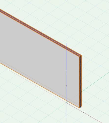
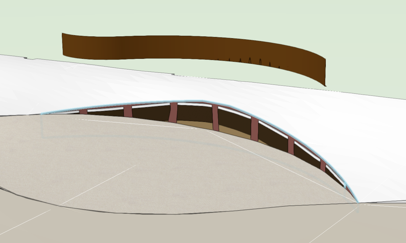
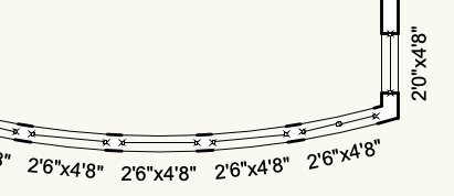
 Hi All, Ive seen images of lots of complex wavy extrudes and curved entities while learning Vectorworks but I am struggling to make a simple curved wall (actually a thin metal edge) that curves in plan and in elevation. Screen shot below of intent. I want the bottom of the wall to be flat but the top to gently rise and fall. Is there an easy way to do this? I've come close by making a curved wall and pulling the end vertices up and down but this tends to affect the whole length of the wall and if you split the wall it results in a pointed peak. Thanks all
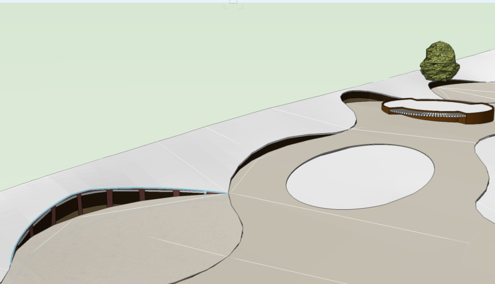

-

Snap to centre off wall component
koenr posted a question in Wishlist - Feature and Content Requests
It would be very usefull to have an option to snap to the centre line off a walls core component. We draw structural plans and we always refer to the middle off the structural parts. Seems like a simple but realy usefull feature 😉 -
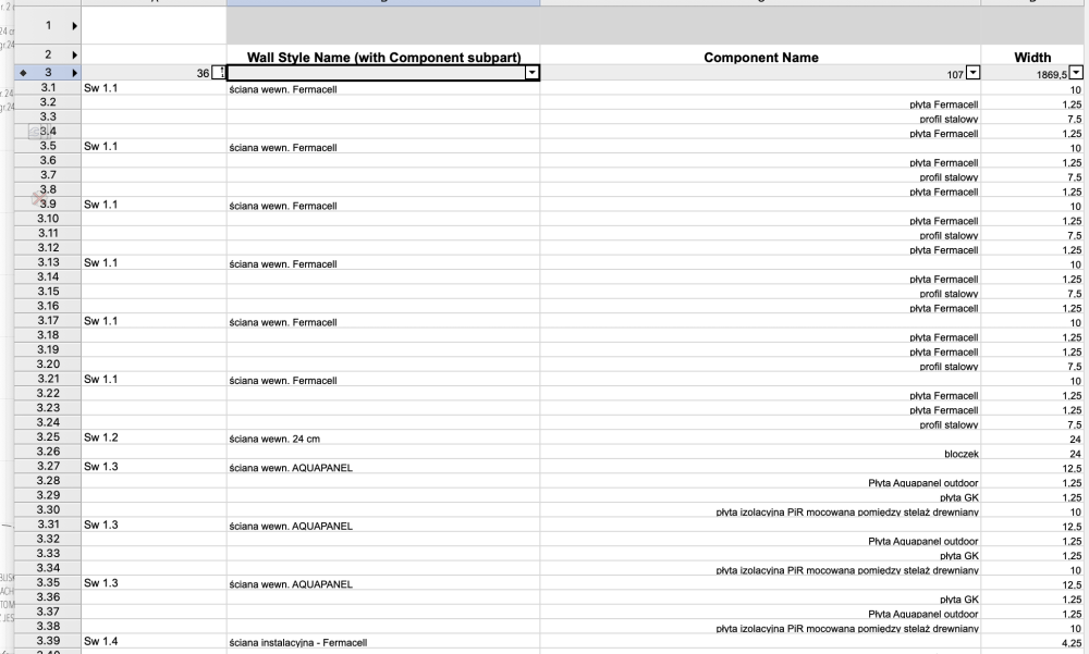
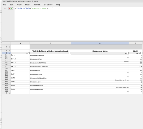
Hi I have got a problem with generating list of wall types that ara used in project. My goal is to achieve in left column "Mark" of the Type than in third list of components that are used. The point is that I do not want to repeat for example Sw 1.1 five times The moment i Click "Sum" option in first column same information About components is lost as on the next photo Thanks for any help with solving that isue
-
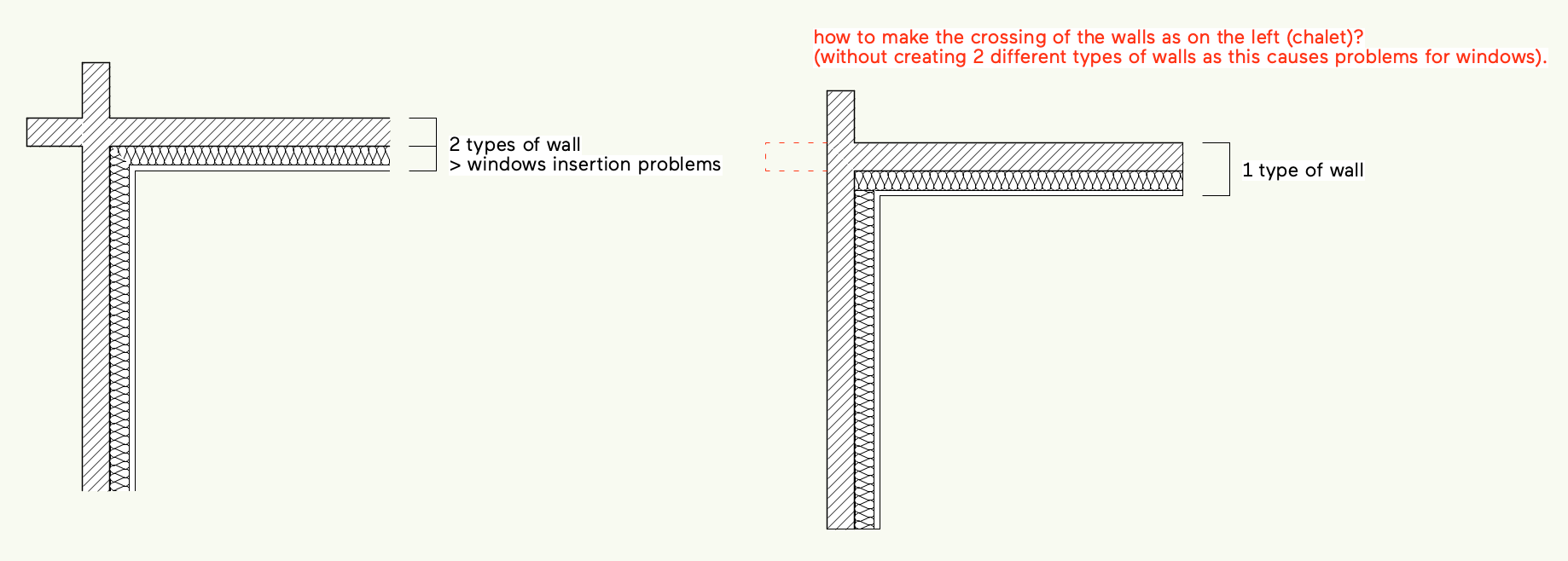
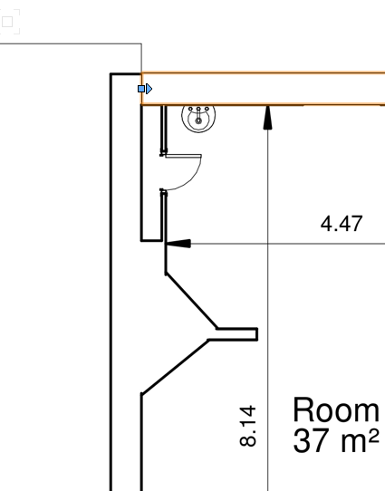
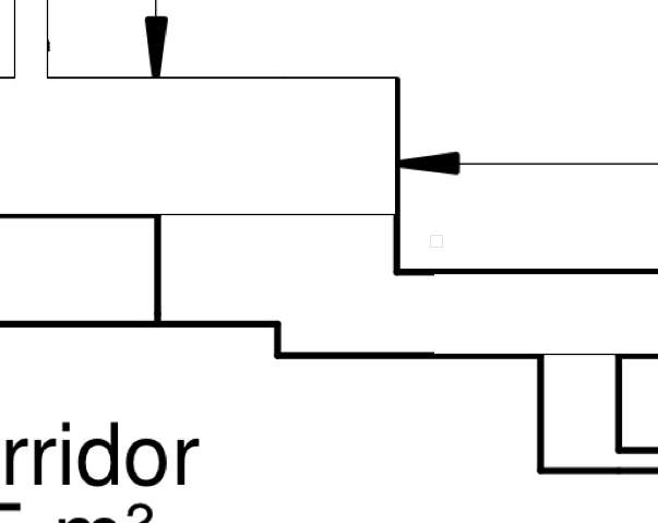
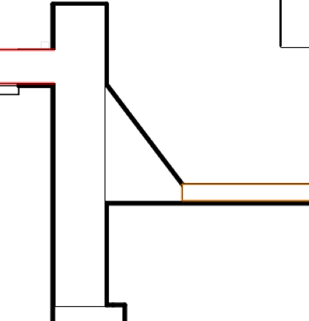
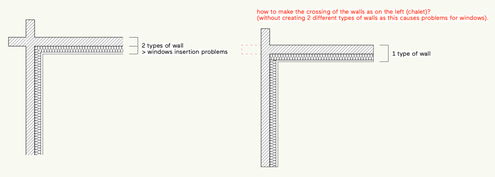
Hi, I’m working on an existing chalet in the french Alps. It has a particular structure with crossing pieces of wood. I don’t manage to make it with Vectorworks. How can I make the crossing of the walls without creating 2 different types of walls ? Did I missed something ? Or maybe that will be a Vectorworks enhancement ? thanks ! LUG-test.vwx
-

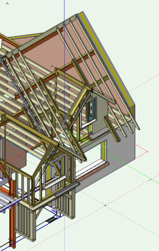
Tool to connect wall, slab and roof components
DaleW posted a question in Wishlist - Feature and Content Requests
I've been trying to connect the below roof and wall so the components join: It would be great if there was a join tool that could connect components between walls, slabs & roofs. this would be perfect for construction documentation. Without this tool I have to trace over each junction such as the above in annotations which is annoying.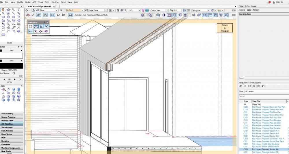
-
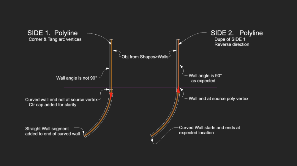
Horsing around with the Create Objects from Shapes >Walls. Source poly (Side 1.) was made with polyline tool: Straight segment on y axis, then Tangent Arc vertices with tangent click on y axis. Side 2. is duplicate, moved over, then direction reversed. The command seems to depend on direction of the source poly. Side 1 funky, Side 2 just right. Known problem/bug? One can delete the walls and reverse the poly(s) and run the command again. Or is there another strategy? Either way, I think the initial direction should not matter. -B
- 4 replies
-
- 1
-

-
- objects from shapes
- walls
- (and 1 more)
-
Hi All - I'm new to tags and trying to use them to display info about two things - 1) Finishes. If I've created a wall and given it a material there are finishes embedded. I'd like to be able to create a label or call out with leader line with finish info for that wall generated by the material. Is this possible? It would save so much typing and ensure accuracy. 2) Steel Members. I'd like to have a label as a call out and leader line that will draw from the type of profile used to create the 3D steel unit, such as W27x94. thanks!
-
 It seems that end-to-end joining of separate, co-linear segments of two exactly similar walls into a single wall object is not possible. Please see the attachments. Even though these wall segments can "join", that is they follow each other when dragging one or the other, they remain separate wall objects as can be seen in the object info palette when both are selected. Being able to join these separate segments into a single wall object would be beneficial for the following reasons: -BIM integrity; since the wall is not going to be built from two different wall elements in real life either, it should be one wall object in CAD as well -ease of editing (style changes etc.) -avoidance of possible rendering issues, "seams" -possible IFC/DWG export implications, if the wall appears as two objects to a reviewer (not sure if this happens if the walls are joined) -general model tidyness; more logical and less objects -quite often one has already drawn two wall objects with windows and doors already inserted, to put all these into a single wall object requires extra steps (extending one of the walls and copying and pasting windows and doors from the other wall). One would think the implementation could be straightforward as long as we are speaking of walls of same style and height. Wall join example.vwx
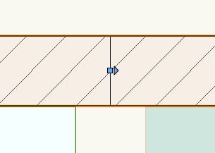
-
 I regularly create landscape retaining walls in my drawings using the wall tool. The landscape wall tool has never really worked for me as it seem to be for very large landscape applications and far more involved to use, at least that has been my experience. I would like to see the ability to add a top cap to a regular wall via the OIP, perhaps providing a cap option of height and width. I have, in the past, used an extruded these but it's a real pain when the wall top is sloped vs level.
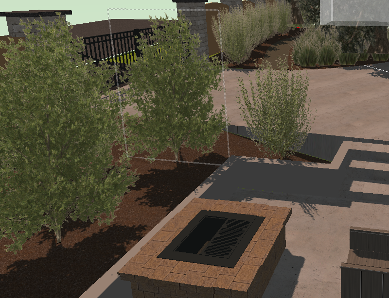
-
I want to separate the interior and exterior walls in my file into two separate wall schedules. All the exterior walls have "Exterior" checked in the wall style (see attached screenshot) and that data, I think, is Pset_WallCommon - IsExternal=True. Can I set the database header to exclude or include all items with Pset_WallCommon - IsExternal=True?
-

Wall With Interchangable Assemblies
Tom Klaber posted a question in Wishlist - Feature and Content Requests
This is a little complex, as it requires a subtle conceptual shift in the way walls and wall styles work - but I think it would be worth it. The wall styles are great, but when you get deeper into DD - you realize you need way too many to cover all the situations you need. If I need three stud sizes (1,2,3), and three finish assemblies (A,B,C) I need 18 wall styles! - A1A, A1B, A1C, A2A, A2B, A2C, A3A, A3B, A3C, B1B, B1C, B2B, B2C, B3B, B3C, C1C, C2C, C3C. I think the equation is (nF(nF+1)/2)*(nC). Where nF is the number if finish assemblies, and nC is the number of core assemblies - (Now known as Tom's Equation. Math people please correct if I am wrong). This can get out of hand quickly. Obviously, you do not necessarily need every combination - so your true total will less than Tom Equation - but the issue remains. We realized this when doing our wall type pages and started to develop a new wall type system that I think holds the answer. Rather than every wall being a fixed style that has to account for every combination of finishes, walls should be broken down. Walls would be composed of mixed and matched assemblies consisting of 1 core or structural assembly and 2 finish assemblies. This could be handled in a similar way to how the Rendering tab thinks of walls: core, left, and right. Right now - the only way to handle wall styles is to dumb it way down. We try to lump all finish assemblies into GWB / Stone. Even with that - we usually have at least 5 different core assemblies, then several rated versions - not counting exterior wall constructions. We can quickly balloon to 20 - 30 wall styles, which is pretty cumbersome and even with that do not achieve the degree of precision we would like. If the finish schedule and wall styles are tied together and controlled via the OIP for the wall - rather than the space object, you can get robust control that easily scales as a project progresses. The project could start with 1 finish assembly, then move generic categories, then when in CDs, the full finish schedule could be applied to walls. The idealized future benefit of this would be the ability to paint bucket finish assemblies onto the core assemblies without having to change the wall style. As an added benefit to the increased precision, this would then let VW 'know' precisely what finish is being called for and then schedule that information, create keyed finish plans, and display the wall with dimensional accuracy. -
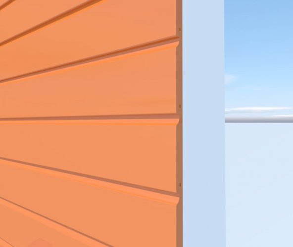
With walls I am sure there are many users who would want to see more realistic Wall Coverings instead of the current Texturing which has been around seemingly for ever. This image shows what can be done with an existing tool - Create Planar Display - to produce an accurate siding weather board. The second image shows metal siding/ roofing material. How difficult is it then to extend this and produce realistic wall coverings.

-
This might be an easy one. I just can't remember the solution now in my old age. Or maybe a new problem with new hardware new OS. How do you get the jamb lines to appear in window objects inserted in a Round wall?
-
Hi, I am trying to draw a wall similar to this Has anyone got some tips?
-
I am new to V2020 and have issues with projecting walls heights with Stories. I used to be able to just set the wall height under "Tools / Organization / Design Layers / Wall Height". Apparently I need to set the heights under "Stories", but i do not understand it and there doesn't seem to be a tutorial for this. Help!! Thanks.
-
As we all know when we draw walls, floors (slabs) and roofs the component portion of each object representing lumber is a monolithic object that in itself can only give area and volume. How does one determine board feet or the number of joists, studs or rafters required from the data we can retrieve from these objects. A formula of course. Would anyone care to share how that is done? I haven't figured it out yet. I'd like to get estimating materials worked out more for the company I work for using the models we create. More BIM! Thanks.
-
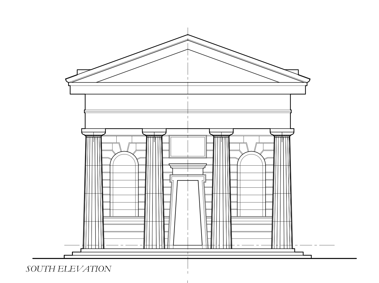
 Hi, I am wanting to create a detailed building showing the unique brickwork on the facade of the building. How would I do this in the most efficient way? Below is a screenshot of the elevation of the facade. Would be great if anyone can help. Thanks
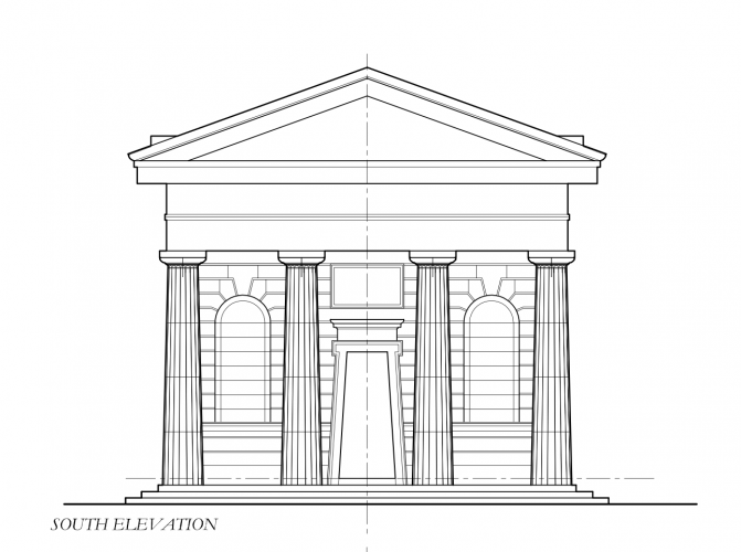
-
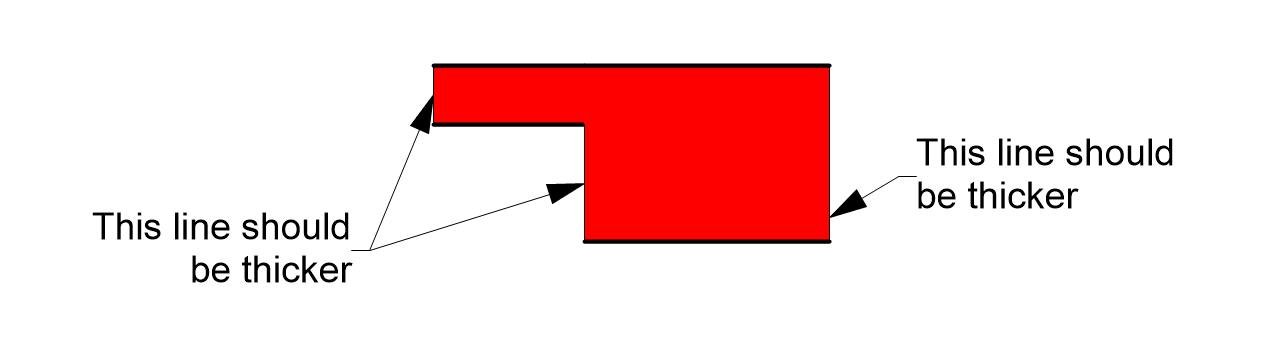
 Hello, I have a simple problem. I want to connect two walls with the same component (all attributes are connected with a class) to create one wall with various thickness. As you can see in the picture VW recognises ends correctly, but uses two different line styles - for the outer and inner face as defined in the class and for the endings much thinner. Any hints? WallConection.vwx
-
 Hi, So, a couple of thoughts: 1. If I combine all walls, slabs, pillars and stuff to one piece of combined solid, will this make a lighter file? 2. If so, how do I do this? I want to make one piece of solid made out of all the walls and slabs I've created. 3. Is this even a good idea? I'm making an arena, so there's gonna be a lot of stuff in the final file, so it needs to be lightweight and easy to understand. Thanks!
 -

Display detail levels (Walls in particular)
Asemblance posted a question in Wishlist - Feature and Content Requests
I like the introduction of the Display detail levels in 2019, but do miss the old 'on/off' switch for wall components to display in a viewport. I'd like to see this returned as a simple control because: 1. Less prone to error/less opaque (If I turn the detail level down to low, what else may turn off in my drawing without me noticing it..?) 2. More customisability. You may want to display a viewport without the wall details, but with other details showing. -

Walls grey in resource manager and model 3D view
thinkingpencil posted a question in Troubleshooting
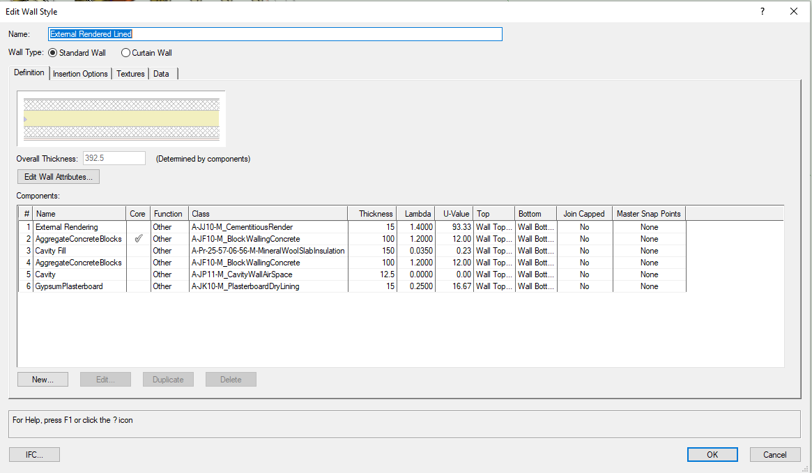
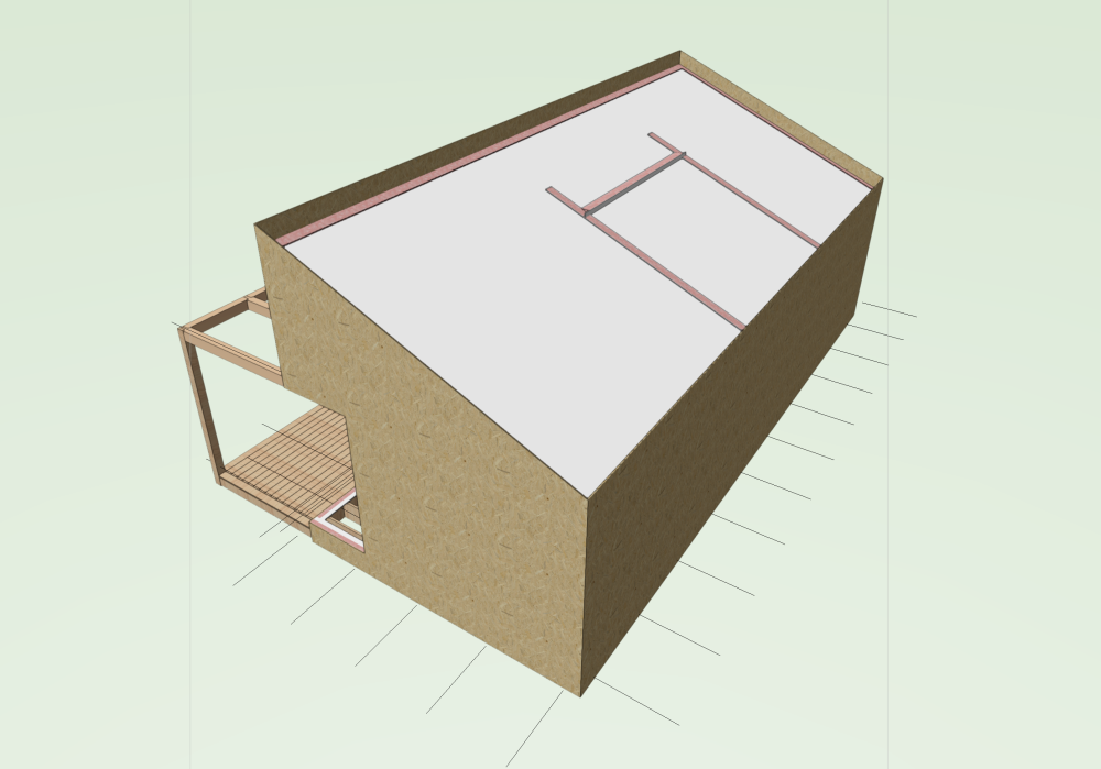
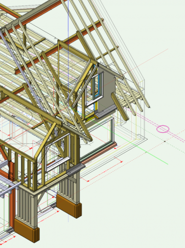
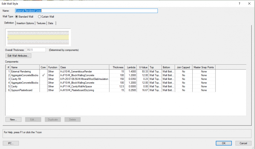
Good morning all. Many walls are greyed out in resource manager. And in the model. But in a previous saved copy of the same file they are not. See both here. I can't remember changing settings like opacity, render options or view/layer options/grey others. None of these are set grey. I have searched the community board without solution. The wall is classified A-G251-M_ExternalWall. I attach its components. Same problems apply to my internal wall class A-G252-M_InternalWall. So I think it may arise from one of the common components? Therefore I have also looked at component class settings within the walls, to make sure none of them are set to less than 100% opacity..they are all 100%. Note other walls are rendering OK. Must be a setting, but which one?! Thank you for any help. I am running 2020 SP4 (build 550627) (64-bit).
-
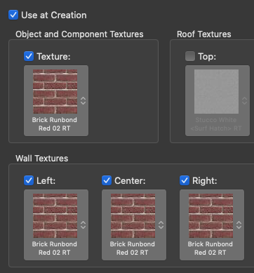
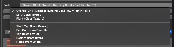
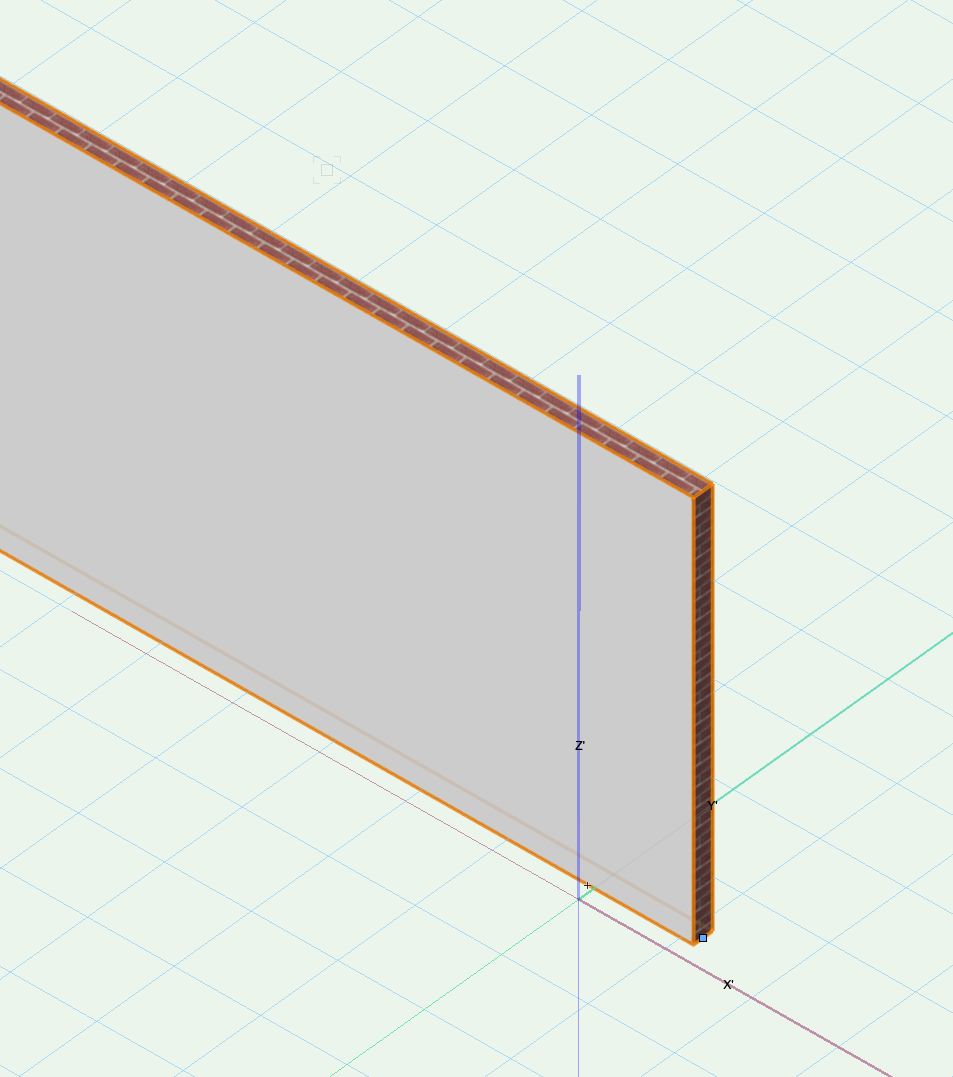
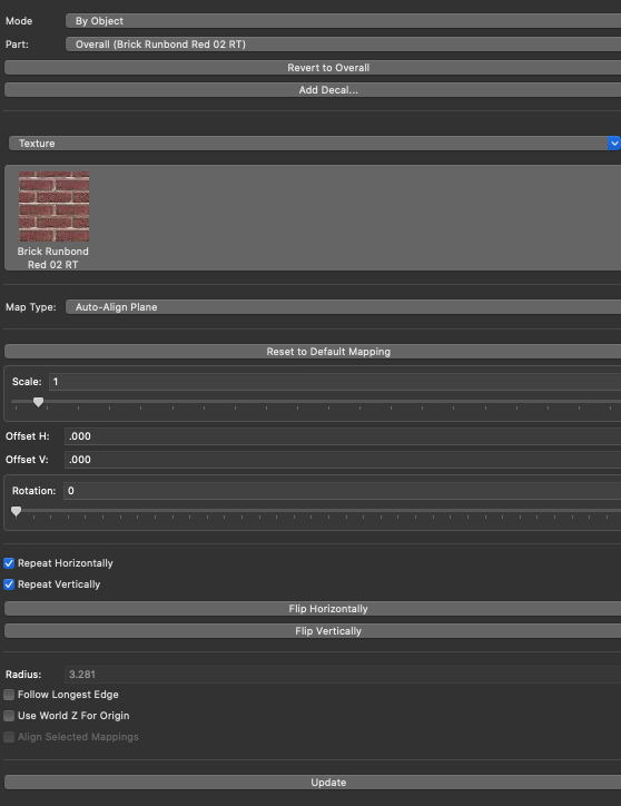
This is a weird one - if I apply any texture to an unstyled, un-classed wall, it only applies to the edges. This is in the default None class. My OIP settings are setup for Overall, Auto-Align Plane If I instead create a class and put the wall in that class, and apply a texture "At Creation" it works just fine: My understanding is if you drop a texture on a wall, it will apply to all faces, not just the edges. If I go to the OIP and manually select "Left" and "Right" and "Revert To Overall" for each Part - then the texture works properly. In other words, it seems like my Unstyled wall defaults to the "Left" and "Right" as Class Textures instead of Overall. Am I missing something? Is there some weird default setting?