Search the Community
Showing results for tags 'lineweight'.
Found 6 results
-
Hello, Is it correct that you can only overwrite the outline of the wall component in section an floor plan but not in isometric views by class? So we have to set the class existing-wall- exterior to 0.10 and then overwrite the class in floorplan to something like 0.35 mm? And not the other way round (class with 0.35) and viewport class overwrite with 0.10 to get a fine line in an isometric view?
-
Hello, this is the first time I try to work with Vectorworks in 3D. When creating a section viewport I see the wall with a VERY thick line in one floor and a very thin one in the other floor. Does anyone understand who's going on? I'm using the same wall style in both floors. Gal OMZ_Sections.pdf
-
Hi everyone, I cannot seem to work out why my lines won't change thinckness. Might I be setting the values in the script wrong? The attached screenshot shows attributes of an example line I need to change. It's thickness is 0.25, and just to see the change clearly, the new thickness would be 1. What am I doing wrong please?? The script otherwise compiles. PROCEDURE LineWeightChange; { © Petri Sakkinen 2008 } CONST { substitute these with the required values } oldWeight = 0.25; newWeight = 1; PROCEDURE ChangeIt (h : HANDLE); BEGIN SETLW(h, newWeight); END; BEGIN FOREACHOBJECT(ChangeIt, LW = oldWeight); END; RUN(LineWeightChange); Thanks for helping!

-

Inconsistent behavior of slabs attributes (or I am missing something)
Stéphane posted a question in Troubleshooting
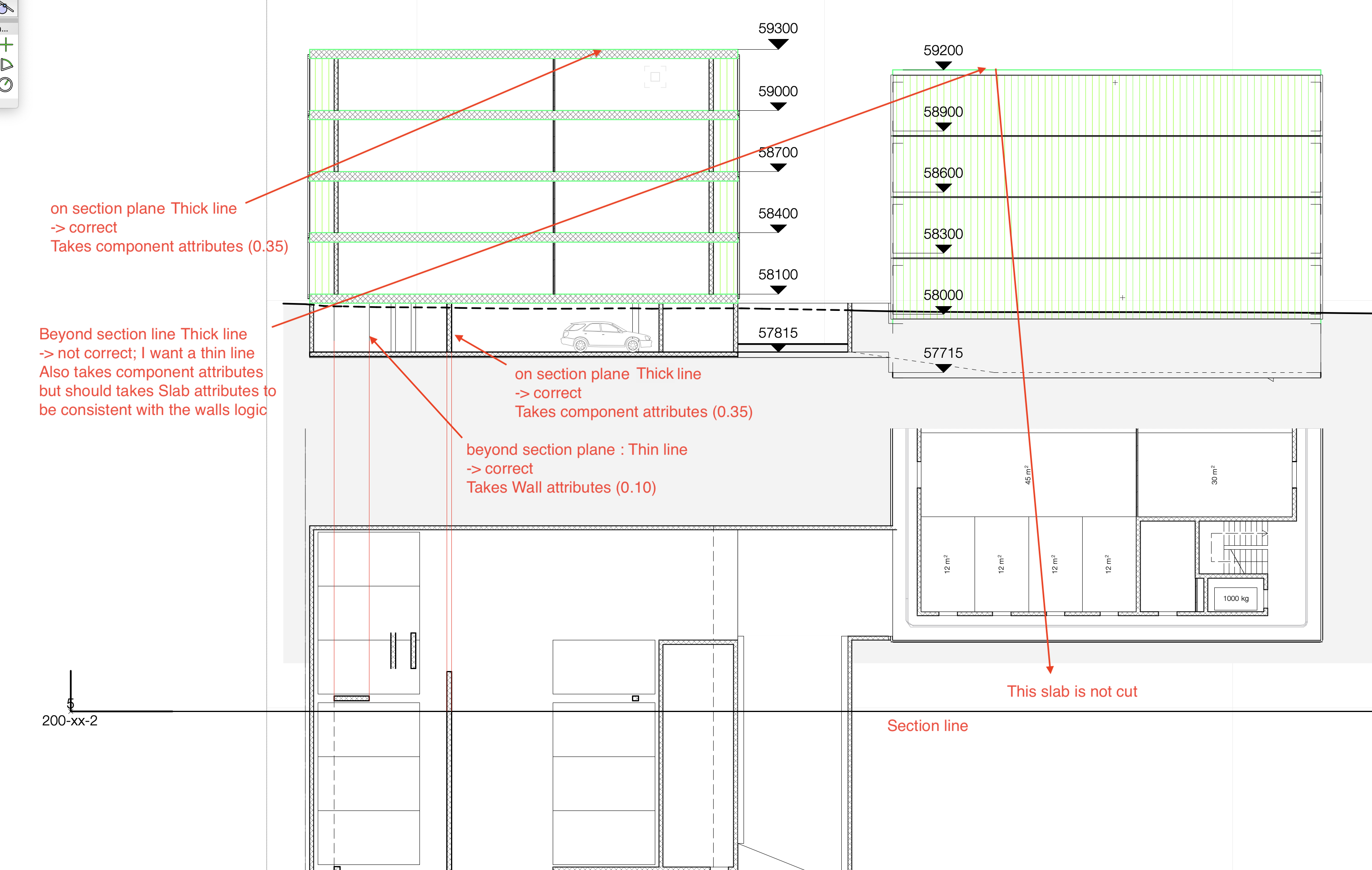
Hello, I'm working on my workflow and there are still little things that I don't understand... A cut wall takes its component attributes and a wall beyond the section line takes its wall attributes. Somehow, this logic doesn't work on slabs. Why ? Am I missing something ? Is it a bug ? Is it as it should be ? My general problem is the following : Objects that are beyond section line need to have thin lines (0.05-0.10) Objects that are cut by the section line need heavier lines (0.18-0.25) Important objects (like structures) that are cut by the section line need even heavier lines (0.35-0.50) I haven't found yet the way to do it ! How to achieve this ? This is something I need to produce proper architectural plans. A workaround I am still using is to set a class attribute for Object Beyond Section Line in Advanced Properties. Issue with this workaround : - Surface Hatch will have the same color as other objects beyond section line (but it is a no go because I want my surface hatch to be colored and other objects to be black) Please see below a commented screenshot to illustrate my issues... I would appreciate your help and/or advice on best practice.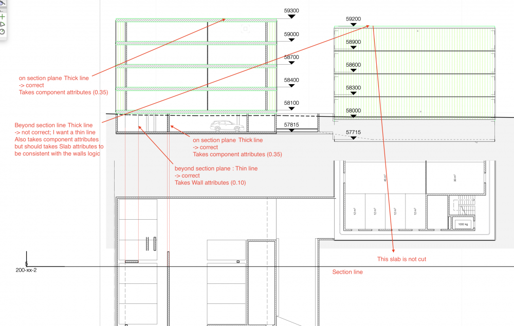
-
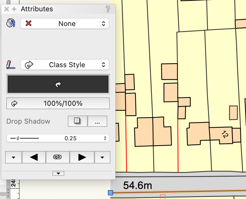
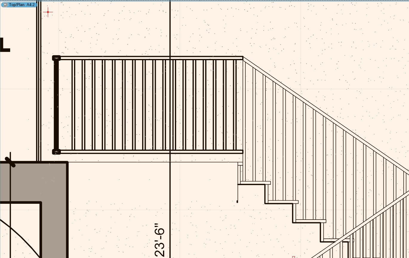
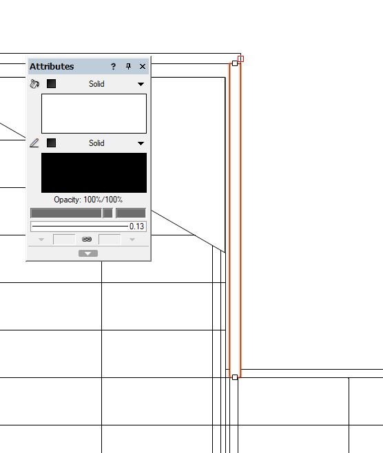
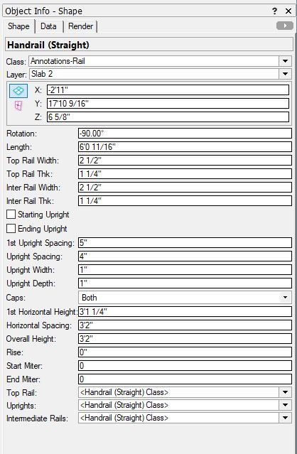
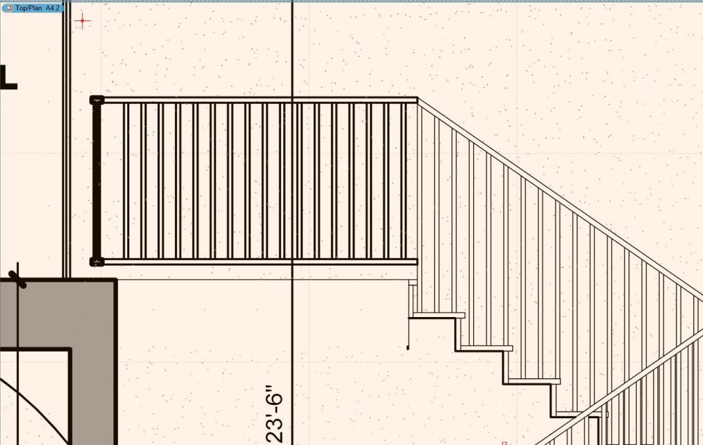
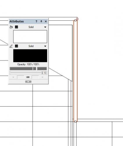
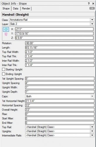
Hey guys, I'm just trying to change the line weight of a hand rail object in the elevation/section viewport. I'm sure this is possible, however I haven't been able to find the solution. My desired lineweight is 0.13mm, however it displays thicker in elevation/section view. I've included images of the OIP and attributes. The layer that the object is placed on is set to 0.13mm, but as you can see this is not the case. Thanks, Raymond
-
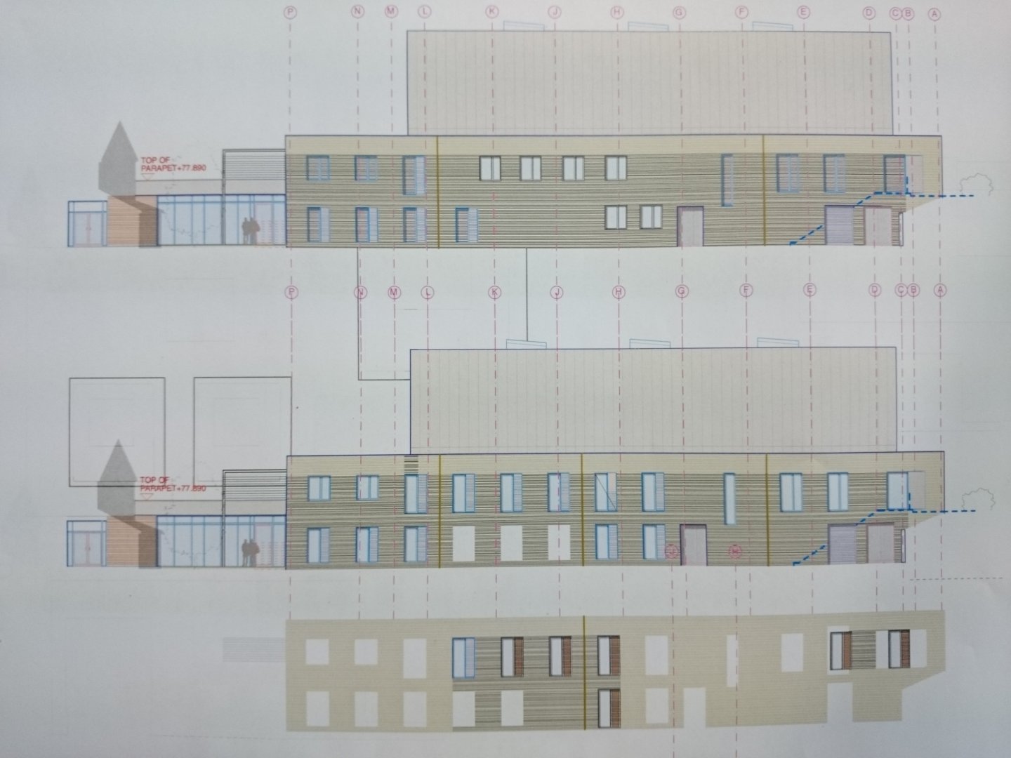
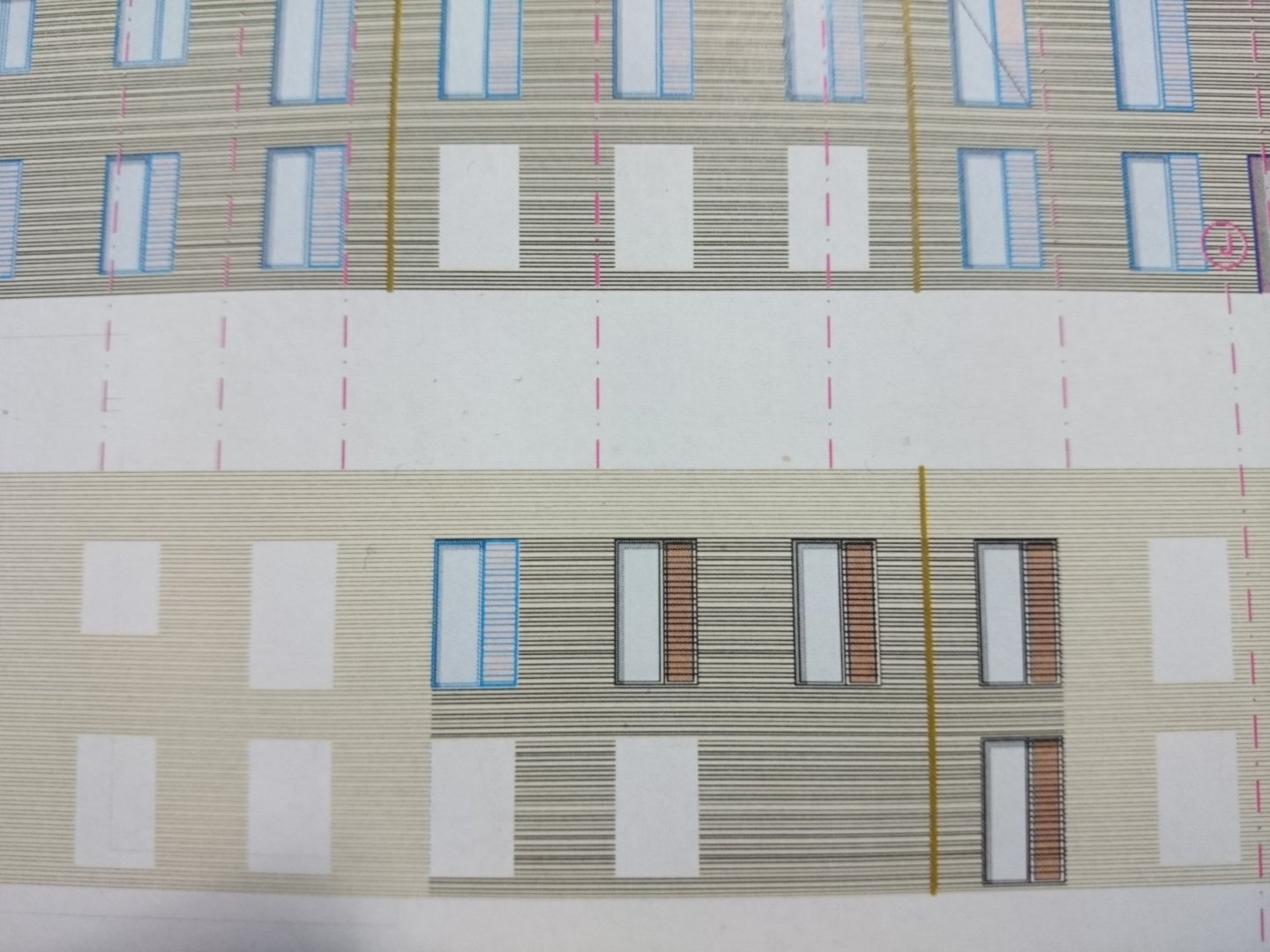
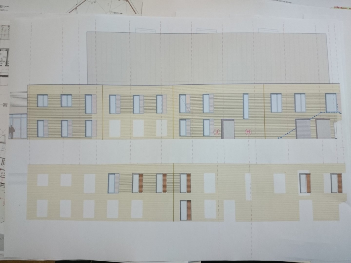
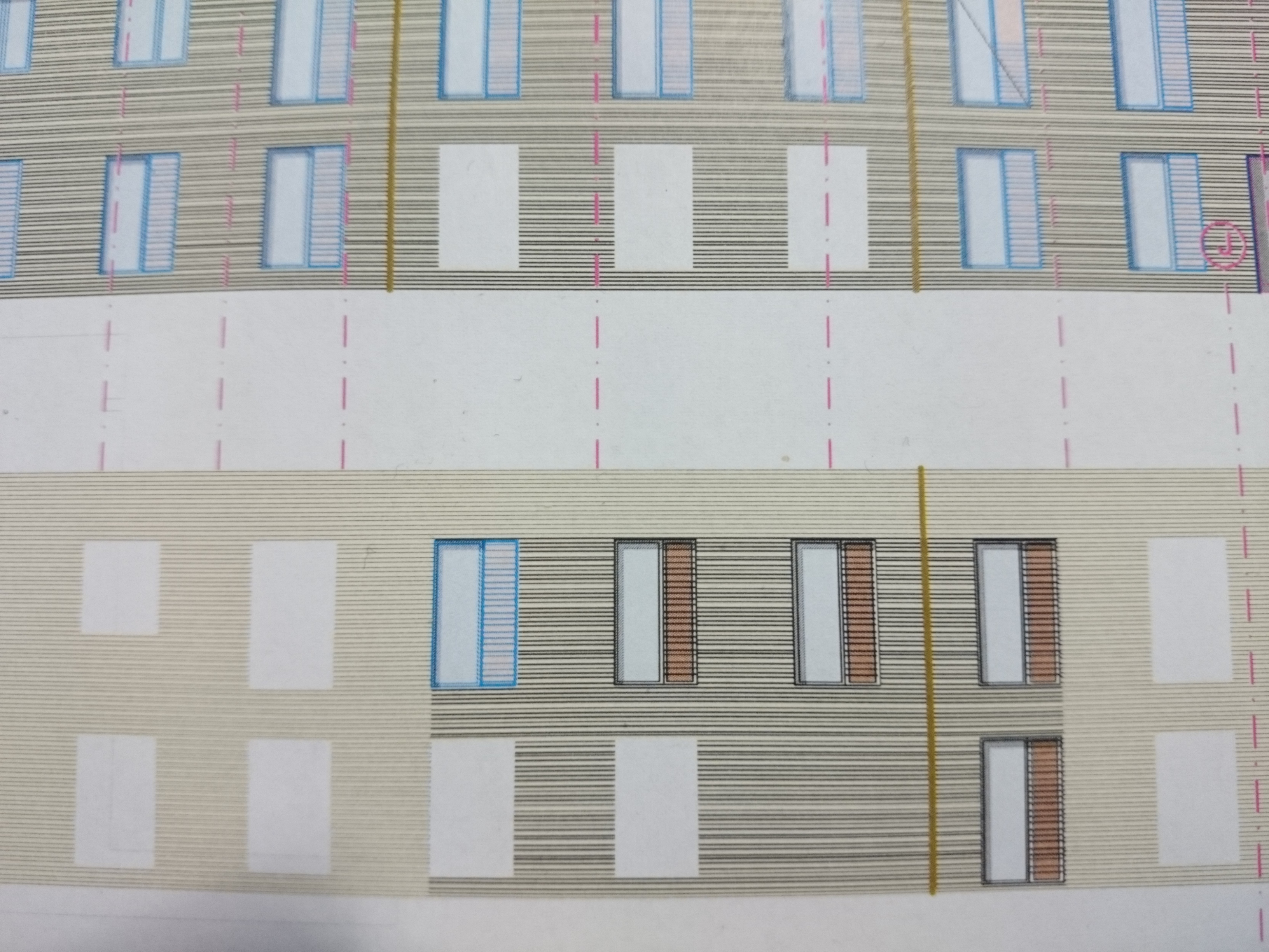
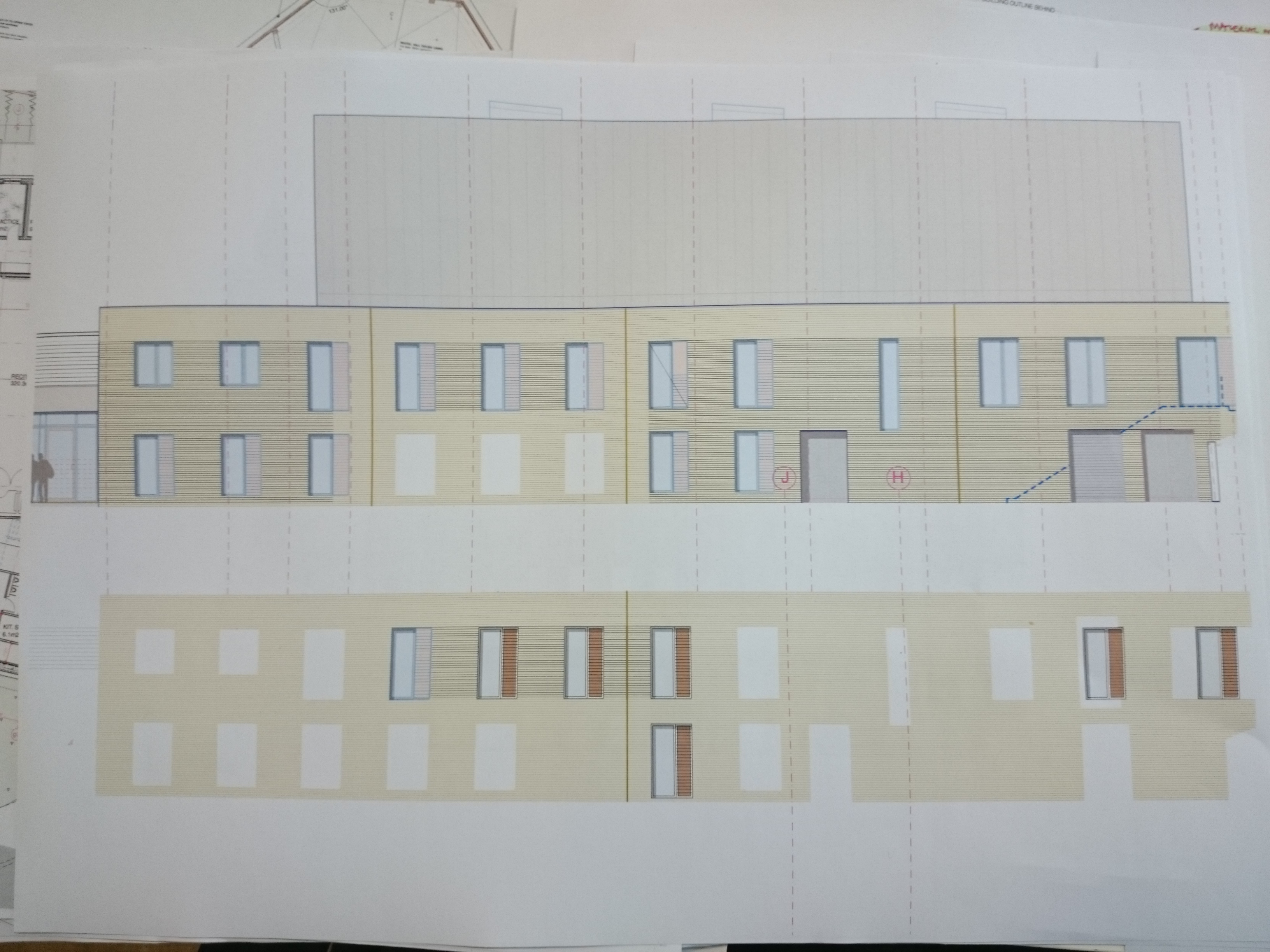
Hi, We are having some serious problems with Vectorworks printing/exporting to .pdf at the moment, where lineweights change depending on the prescence of other geometry nearby. We have tried printing from different mac systems to 2 different printers, using old and new print drivers, both with the same issue, on vwx 2016 and 2017. I have tried printing with different DPI's directly from vectorworks, and from a pdf, both showing the same issue. I have also tried creating a new file and recreating the geometry in there, with the same issue. Screen shots attached - what you are seeing is a simple hatch of 0.05 lineweight horizontal lines at 75mm c/c, with no hidden geometry's, copied/recereated several times with ungrouped, grouped and symbol windows scattered throughout (which seem to cause the banding). Printed also at different scales, still with the same issue. Any ideas?? Thanks! Anthony